Sections
- Introduction to industrial wastewater evaporators
- Use of industrial vacuum evaporators
- Types of wastewater evaporators
- Our evaporators Catalogue
- Factors to consider when choosing an evaporator
- Parts of a vacuum evaporator
- Installation of a vacuum evaporator
- Maintenance of vacuum evaporators
- Encrustations and corrosion
- Cristalizadores industriales al vacío
- Encrustations and corrosion
- The basics of vacuum evaporation
- Properties of the liquid to be evaporated
- Basic calculations in an evaporation system
- Brief history of industrial evaporation
Introduction to industrial wastewater evaporators
Industrial wastewater evaporators are an efficient, simple and cost-effective technology to treat and reuse wastewater.
This guide aims to ensure a better understanding of industrial evaporators and highlight the key aspects to consider when selecting a wastewater evaporator manufacturer, or a supplier for a wastewater treatment plant that includes one or more vacuum evaporation units.
Before going deep into the details of the technology, we wish to answer some of the most frequently asked questions about vacuum evaporation systems that our customers raise.
How do wastewater evaporators work?
A vacuum evaporation plant separates water from contaminants with high boiling points.
The wastewater enters a boiling chamber and is heated until the water molecules turn into vapour. The contaminants are left behind while the vapour is collected, cooled and condensed in a heat exchanger. The entire system operates in vacuum conditions, meaning the wastewater boils at lower temperatures.
What is vacuum evaporation used for?
Vacuum evaporation is perfect for treating and/or recycling the wastewater generated in the production processes of a wide variety of industrial activities. Wastewater evaporators are often combined with other processes to create a full wastewater treatment system.
The main reasons to opt for vacuum evaporators to treat wastewater are:
- Recover a large volume of clean water for reuse, or safe discharge to the environment.
- Optimized minimization of the final waste to be sent to waste management companies, which represents significant cost savings.
- Recovery of valuable materials present in the liquid waste, such as raw materials or recoverable by-products.
What are the benefits of industrial water evaporators?
Vacuum evaporation systems offer a set of advantages for wastewater treatment and resource recovery:
- High efficiency, since a very high percentage of clean water is reclaimed, reducing the volume of sewage and waste management costs.
- It is a direct, easily operated process.
- It is robust, durable technology requiring little maintenance.
- Cost-effectiveness: low energy consumption.
- It is versatile technology that allows wastewater to be treated with little or no pre-treatment, including hazardous effluents that are difficult to manage.
- It allows zero discharge, or zero liquid discharge (ZLD), to be obtained as distilled water can be reclaimed and recycled as process water, which helps plants to comply with discharge regulations and provides a potential source of cost saving and generation of extraordinary income.
- Resource recovery: valuable materials can be reclaimed and recycled, including metals, salts, acids and active pharmaceutical ingredients (APIs), to name a few examples.
Why should vacuum evaporators be considered?
Discharge regulations are increasingly strict and this translates into an increase in the operating costs related to treating industrial wastewater. This entails a new challenge for manufacturers who are obliged to manage their liquid waste and maximise the efficiency of their production processes.
A vacuum evaporation plant offers a response to these challenges as it is a highly efficient technology for treating industrial wastewater:
- Recover more than 95% of clean water that can be reused
- Recover valuable by-products that can be sold or reused
- Minimises the volume of waste to be sent to the administrator given its high capacity for concentrating contaminants
As well as offering these wonderful results, vacuum evaporation allows transport and liquid waste management costs to be reduced, in addition to costs for manpower and chemical agents, since it is a technology that can operate automatically, requiring little supervision.
Wastewater treatment systems that use industrial vacuum evaporators are an excellent choice for manufacturing processes that may expand or change in the future.
When are vacuum evaporators the best choice for industrial businesses?
- You want to implement a circular economy system to manage your waste
- You want to reclaim resources dissolved in your effluents and generate cost savings
- When there is scarce water available
- You want to reuse water
- You want to minimise the volume of waste to be managed
- You want to significantly reduce waste management costs
- You want to generate income by transforming waste into by-products
- You want to reduce the need to store large volumes of waste
- You want to reduce greenhouse gas emissions when transporting waste
- Demanding effluent discharge regulations must be observed
What types of wastewater are difficult to treat with technology different to evaporation?
Vacuum evaporators are a competitive and efficient solution for treating wastewater containing contaminants that are particularly difficult to separate from water. These are usually effluents that cannot be treated using more conventional methods, such as biological, physical or chemical processes. This typically occurs when the wastewater contains:
- Brines with a very high concentration of salts
- Non-biodegradable compounds
- Substances that are toxic for microorganisms
- Wash water
- Landfill leachate
- Wastewater from die casting
- Depleted baths from surface treatment
- Emulsions from machining and other processes
- Used developing solutions and fixing agents
- Concentrates from membrane separation processes
- Wash water from reactors, mixers and tanks
- Eluates from washing ion-exchange resins
- Etc.
As well as being used to treat effluents, evaporation is also widely used in the food industry to concentrate many kinds of substances that are sensitive to the heat: to concentrate fruit juices, to produce condensed milk, to remove alcohol to obtain alcohol-free beer, etc.
What is the difference between evaporation systems and other technologies?
Evaporation is a clean process that does not add more contaminants to those already present in the liquids to be treated. The equipment takes up little space, is relatively easy to maintain, and lasts for a long time. Furthermore, the condensate obtained is usually of high quality, allowing it to be reused in many industrial processes or disposed of with no contamination problems.
What types of industrial evaporators are there?
There is a wide variety of industrial evaporators and the choice of one model or another depends on various factors, including variables such as the effluent's composition, the flow to be treated, the energy sources available, the space available, and the client's environmental or economic objectives.
This guide includes a chapter dedicated to the main evaporator models, which are supplied by almost all manufacturers, along with their characteristics and main uses. In summary, they can be classed as follows:
- Hot water or vapour evaporators:
- Heat pump evaporators
- Multiple-effect evaporators
- Mechanical vapour-compression evaporators (electrical)
- Falling film evaporators
- Forced circulation evaporators
- Natural circulation evaporators
- Membrane distillers
- Atmospheric evaporators
How is the performance of a wastewater evaporator maximised?
Selecting the right materials, understanding the components of the vacuum evaporator and carrying out appropriate maintenance will allow you to optimise the evaporation plant’s performance, as well as maximise its useful life.
Use of industrial vacuum evaporators
Vacuum evaporation is a unitary operation that consists of concentrating a solution by separating the solvent via boiling. It is carried out at a pressure lower than atmospheric pressure, meaning the boiling point is lower than the temperature that corresponds to atmospheric pressure, with the subsequent energy savings. This technology allows liquid effluents to be treated efficiently, cleanly, safely and compactly.
In the field of treating effluents, this technology is suitable, above all, for complex discharges with refractory COD, or that require special treatment, or that are difficult to handle (aggressiveness, viscosity, etc.).
Unlike other conventional treatments, such as physical and chemical processes, no coagulant/flocculant reagents are required, nor must the pH be adjusted, meaning the solvent and solute can be easily separated with no effect on their characteristics.
This technology is becoming more widespread in its use by companies that are increasingly aware of the need to implement a sustainable environmental policy as it allows them to minimise the volume of discharge sent to external management companies, which in turn enables them to reduce the cost involved. As a result, it can be viewed as a complementary alternative to external waste management.
Evaporators are used in a wide variety of processes, including those for pharmaceuticals, food and drink products, pulp and paper, chemical products, polymers and resins, inorganic salts, acids, bases and a range of other materials. There are many kinds and variations in evaporators and the option most suited to a particular form of use will depend on the product’s characteristics and the desired results.
Types of wastewater evaporators
In vacuum evaporators, generation of the vacuum causes a reduction in the liquid's boiling point. Consequently, it increases the difference in temperature between the heating agent and the liquid. Thus, the heat transfer speed in the evaporator increases.
This phenomenon is described by the Antoine equation, establishing a ratio that allows us to know the boiling point of a liquid at different pressures
where 𝑃 is the working pressure expressed in mmHg, 𝑇𝑏 is the boiling point and 𝐴, 𝐵 and 𝐶 are coefficients that are empirically determined for each substance.
In the range of boiling points from 1 to 100°C, the coefficients are:
𝐴 = 8.07131; 𝐵 = 1730.63; 𝐶 = 233.426
One of the elements that determines important operating differences between the types of industrial water evaporators is the technology they use to heat the effluent to be evaporated, which in turn determines the operating costs.
The most common systems for creating a depression or vacuum inside evaporation vessels are:
- Liquid ring vacuum pumps.
- The Venturi ejector.
Heat pump vacuum evaporators
The operation of heat pump evaporators is based on the cooling cycle of a gas in a closed circuit.
The cooling gas is compressed by a compressor increasing its pressure (19 ÷ 21 bar) and temperature (70 ÷ 80°C). It circulates through the evaporator's own heat exchanger, transferring heat to the liquid and heating it until the boiling point is reached and maintained. Given that the evaporator works at a very low pressure (40 mbar), the boiling point is 40°C.
The coolant leaves the evaporator's exchanger and, via an expansion valve, it is decompressed (4 ÷ 8 bar) and cooled (10 ÷ 15°C). When passed through a second heat exchanger (condenser), this same cooling gas makes the evaporation vapours condense at a temperature of around 40°C, transferring heat once again to the cooling gas, increasing its temperature just before sending it through the compressor once more and repeating the cooling cycle.
The same coolant allows the intake flow to evaporate and the vapour generated to condense, meaning the system does not require other heat or cooling sources. This makes the process highly advantageous from a financial and management standpoint. In addition, it has low maintenance costs and is fully automated, assuring constant quality of the distillate by providing full separation of metals and surfactants. These evaporators also have a foam control system.
This technology is perfect for treating flows of corrosive, encrusting or viscous liquids that are not high. Its operation amounts to energy consumption of 130-170 kWh per cubic metre of distillate. These evaporators also offer a significant reduction in the COD in the distillate and a low amount of discharge concentrate.
Mechanical vapour recompression (MVC/MVR) evaporators
This technology is based on recovering condensation heat from the distillate as a heat source for evaporating the intake flow. To do so, the temperature of the vapour generated during evaporation is increased by mechanically compressing it. When passed through the evaporator's exchanger, this compressed (and therefore overheated) vapour achieves two goals: (1) it heats the liquid to be evaporated, and (2) it condenses, economising the use of a coolant.
A mechanical vapour recompression evaporator is designed to efficiently treat industrial waste effluents from production processes and those refused from wastewater treatment plants, with a low energy cost. Its high efficiency is owed to the use of a rotary blower or vapour compressor that allows the latent heat of the same to be increased via volumetric mechanical compression, with a small amount of electrical consumption from the motor operating said compressor.
This heat from the compressed vapour is transferred via a heat exchanger to heat the effluent to be evaporated and as a result, it will allow the vapour to condense and produce the distilled water. By working with a vacuum, generated by the rotary blower or with the help of an auxiliary vacuum pump, the boiling and vapour temperatures vary from 60ºC to 90ºC.
When passed through the evaporator's exchanger, this compressed (and therefore overheated) vapour achieves two goals:
- It heats the liquid to be evaporated.
- It condenses the evaporated flow, economising the use of a coolant.
Natural circulation evaporators
These are very competitive pieces of equipment that are suited to cases where low vapour production (10-120 l/h) is required.
Natural circulation evaporators operate with electrical energy and are easy to use and maintain. Furthermore, they are an excellent investment given their combination of distillate quality, high tech and robustness.
Forced circulation MVC vacuum evaporators
Forced circulation evaporators use a heat exchanger immersed in the fluid to be evaporated. Given the condensation from the compressed vapour inside the pipes immersed in the liquid, they generate convective heating within the liquid.
As they have an external case/pipe (or plate) exchanger, they use a high flow circulation pump to produce a high flow that reduces sedimentation and encrustation in the heat exchanger.
Furthermore, by working at a pressure higher than that in the boiling chamber, no evaporation occurs inside it. If a vacuum pump is added, it can operate at lower temperatures, up to 50°C.
Falling film evaporators
These are highly efficient, compact evaporators that have a lower energy consumption than natural and forced circulation evaporators. They have a built-in cleaning system and can produce up to 4,000 l/h.
Thanks to their high-performance separator, they generate almost no foam. In addition, the interior division between the hot and cold areas reduces the wear and tear suffered by control and adjustment equipment.
They have an automatic built-in cleaning system that ensures their continual availability. All important process settings are viewed on a touch screen and their design, with large doors on both sides, facilitates their use and maintenance.
This is a highly efficient technology used to obtain high-quality water from an effluent with a high concentration of contaminants. Falling film evaporators use thermal energy, but when operating in vacuum conditions the boiling point is reduced, meaning energy consumption is also reduced.
Multiple-effect vacuum evaporator (MEE)
This technology consists of a set of interconnected evaporators in which the vacuum progressively increases from first to last. At first, this makes the boiling point decrease, meaning the vapour generated in an evaporator (or effect) can be used as heating fluid for the following effect, causing a waterfall effect. Lastly, the distillate is condensed via a cooling tower that requires negligible water consumption.
These evaporators use hot water or vapour from an external circuit as an energy source, which allows excess residual flows of heat to be fully maximised.
They are usually units comprising one (single-effect evaporator), two (double-effect evaporator) or three (triple-effect evaporator) stages.
In a single-effect evaporator, the enthalpy of the vapour produced is not harnessed as this vapour is not used as a heating element or agent. However, it can be used in a second evaporator if the solution contained in the latter has a sufficiently low boiling point to ensure the difference in temperature between the heating vapour and boiling solution provides a suitable flow of heat.
Looking at a triple-effect evaporator: the vapour produced in the first effect is used as a heating agent in the second, where it is condensed at a temperature higher than the boiling point of the solution evaporated in it. The vapour produced in this second evaporator is taken to a third where it is condensed at a temperature higher than the boiling point of the solution found in it. The water vapour produced in this last effect is collected in a condenser connected to a vacuum system.
If the evaporators are numbered in the direction the pressure is reduced, it would be as follows:
1>2>3
b,1>b,2>b,3
Where 1,2,3 are the working pressures of each effect and b,1, b,2, b,3 are the respective boiling points of each effect.
To heat a multiple-effect evaporation system, hot water or vapour from an external circuit can be used as an energy source, allowing excess residual heat flows to be harnessed (CHP motor cooling circuits, combustion gas recovery, etc.).
The hot water generated by solar thermal collectors and a heat pump can also be used.
Its main advantage over a single evaporator lies in the savings made in terms of heating fluid and coolant. To treat high flows, this is one of the most competitive options available from a financial standpoint.
MEE thermal-vapour compression (TVC) vacuum evaporator
These evaporators use the same layout as MEE equipment to recover latent heat, but they also have a thermo-compressor.
Thermo-compressors consist of a vapour ejector that is fed with high-pressure vapour that injects latent heat into the vapour produced in the preceding stage.
The resulting mix of vapours has a higher temperature and pressure than the vapour in the distillate stream.
The heat said mix of vapours contains is transferred to the next effect. This is a more efficient system, especially when more than three effects are used.
MEE vacuum evaporator in direct contact with membranes. Membrane distillation (VMEMD)
Unlike other membrane separation processes where there is a mechanical (NF, RO) or electrical (ED) driver, this is a thermal separation process owing to the change in state, from liquid to vapour.
The membrane is hydrophobic, which prevents the passage of the liquid state but allows the passage of vapour through the membrane’s pores.
The driver of the process is the difference in the partial pressure of the vapour due to the temperature gradient.
Membrane distillation (VMEMD)
The multiple-effect evaporation developed by Memsys® in 2012 is based on applying modules of machined polypropylene (PP) plates with the securely welded hydrophobic membrane.
Stacking plate modules creates multiple effects with a simple and low-cost design, with no need to use the parts common to conventional evaporators: frame and heat exchanger.
Using an external heat source at a temperature between 70 and 85°C, the liquid to be evaporated is heated in the first effect.
Due to the vacuum effect, the vapour passes through the membrane.
The vapour condenses on the other side of the membrane due to latent heat being transferred to the next effect. In the last effect, the vapour is condensed via an external cooling source. The distillate is produced in each evaporation stage and the concentrate is discharged via pump.
Atmospheric pressure evaporators
They work at atmospheric pressure and the water boils at over 100°C depending on the concentration and type of solute. Bear in mind when selecting the heat source that they have a high energy cost.
To heat the liquid, they use combustion gases, thermal fluids or saturated vapour at a high temperature, which circulate via an immersed heat exchanger. The liquid boils and water and all volatile substances evaporate. When the concentration of COVs is very high, a thermal oxidiser or combustor should be incorporated to burn the volatile substances. This process is known as OXIDATIVE EVAPORATION (OXIVAP).
Our evaporators catalogue
 ENVIDEST LT FC-2Double-Effect Electrical Vacuum Evaporator by Heat Pump
 ENVIDEST MVR FC TFVacuum evaporators by mechanical vapour recompression and forced circulation
 ENVIDEST MFE 1Single effect thermal vacuum evaporators by forced circulation
 ENVIDEST MFE 2Double effect thermal vacuum evaporators by forced circulation
 ENVIDEST MFE 3Triple effect thermal vacuum evaporators by forced circulation
 ENVIDEST MVR FFFalling film vacuum evaporators by mechanical vapour recompression and forced circulation
 ENVIDEST DPM 1Single effect thermal vacuum evaporators
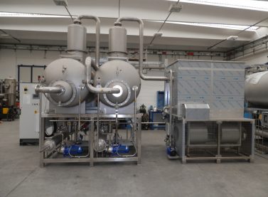 ENVIDEST DPM 2Double effect thermal vacuum evaporators
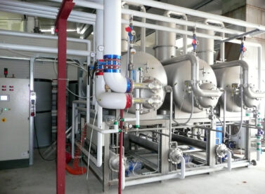 ENVIDEST DPM 3Third effect thermal vacuum evaporators
 ENVIDEST LT VSHeat pump vacuum evaporators
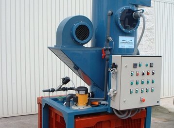 ENVIDEST EAAtmospheric evaporators
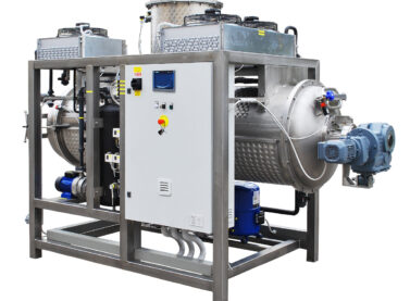 DESALT LT DRYHeat pump vacuum crystallizers
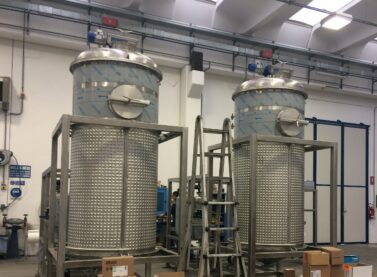 DESALT LT VRHeat pump vacuum crystallizers
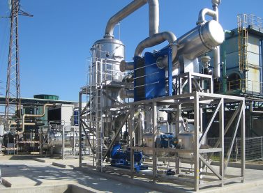 DESALT MFEThermal vacuum crystallizers by forced circulation
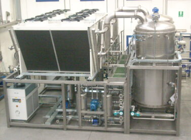 DESALT VRThermal vacuum crystallizers
 DESALT MVR FCVacuum crystallizers by mechanical vapour recompression and forced circulation
 DESALT DRYThermal vacuum crystallizers
 DESALT VTRThermal crystallizers
ENVIDEST evaporators
| Energy input | Model | Q (l/d) | Temp. (ºC) | Type | Consumption (kW/m3) | Use |
| Electrical Heat pump | LT-VS | 125 - 625 | 37 | Heat pump | 150 | Treating industrial effluents Medium flows |
| Electrical Heat pump | LT-DPE | 250-2500 | 37 | Heat pump | 150 | Small volumes of effluents |
| Electrical | MVR-FF | 600-80000 | 90 | Mechanical vapour compression Falling film | 36-100 | High flows Reduced energy consumption |
| Electrical | MVR-FC | 250-2000 | 90 | Mechanical vapour compression Falling film | 50 | Medium flows Low energy consumption |
| Thermal Multiple effect | DPM (1,2,3) | 4000-30000 | - | Horizontal chamber Internal toroidal exchanger | according to no. effects | Medium flows High recovery of latent heat |
| Thermal Forced circulation | MFE (1,2,3) | 15000-200000 | - | Vertical chamber Exchanger casing and external pipes | according to no. effects | High flows High recovery of latent heat |
DESALT crystallizers
| Energy input | Model | Q (l/d) | Temp. (ºC) | Type | Consumtion (kW/m3) | Use |
| Electrical | LT-DRY | 250-1000 | 37 | Horizontal with/without scraper | 250 | Low flows Recovery of concentrated solids and raw materials |
| Electrical | LT-VR | 250-3000 | 37 | Vertical with scraper | 250 | Low flows Treating encrusting effluents High-viscosity solutions |
| Thermal | DRY | 1000-3000 | - | Horizontal without scraper | according to model | Low flows Obtain solids and crystallised salts |
| Thermal | VR | 6000-12000 | - | Vertical with scraper | according to model | Medium flows Concentration of liquid brines |
| Thermal Multiple effect | MEE | 15000-100000 | - | Vertical External exchanger | according to model | High flows Treating brines |
Factors to consider when choosing an evaporator
Evaporation is an operation used to concentrate a solution from a non-volatile solute and a volatile solvent, often water. A portion of the solvent is vaporised to produce a concentrated solution, in suspension or a thick and viscous liquid. Evaporation is different to drying as the residue is a liquid, rather than a solid. Evaporation is different to distillation as there is no attempt to separate the vapour into individual components.
The vapour or the concentrated stream, or both, may be the desired product, therefore, the evaporator must be designed to provide a clean separation of the condensate vapours and the supply.
A suitably designed wastewater evaporator must, at minimum:
- Be designed to effectively transfer heat at high speed with minimal surface to ensure installation, operations and maintenance are cost-effective.
- Effectively separate the vapour from the liquid concentrate.
- Comply with the required conditions for the processed product.
- Produce a product that complies with the required quality.
- Be energy efficient, whenever possible, making effective use of vapour with multiple-effect evaporation or vapour recompression.
- Minimise the fouling of heat transfer surfaces.
- Be built using suitable materials that minimise corrosion.
The critical operating characteristics and the product from the solution to be evaporated are important factors to consider when selecting the type of evaporator most suited to the chosen use.
Sensitivity to heat
Many foods, pharmaceutical products, chemical products and resins are sensitive to heat or high temperatures and they require low heating temperatures, a short time exposed to heat, or both. This can be achieved by the combination of minimising the volume of product in the evaporator, minimising the time spent in the evaporator, and reducing the boiling point to suit the product, making the evaporator operate at reduced pressures. By reducing the internal working pressure, the installation can also operate at lower heating temperatures while a reasonable transfer of heat is maintained.
Fouling
The fouling of heat transfer surfaces is usually caused by the presence of solids in the supply and results in precipitates in the concentrate or product degradation. A slow accumulation of a film on these surfaces will cause a gradual reduction in the overall heat transfer coefficient. Eventually, this will see the process need to be switched off and the transfer surfaces cleaned, which translates to a time of production inactivity and additional maintenance manpower.
Foam
Foam from the product during vaporisation is common. It can vary from a small amount of unstable foam that breaks easily to a highly stable foam that is difficult to break and tends to fill the entire vacuum of the evaporator system. Foam can often be minimised with special designs for the supply inlet (separation of supply of the vapour stream) and the vapour/liquid separation area (special decoupling designs). It can also be done by reducing the boiling intensity of the liquid on the heat transfer surface (operating at a lower temperature or a higher pressure) and reducing the speed of the vapour in the pipes, where permitted by the product purity specifications. Dosing a defoamer can resolve or greatly reduce the issue.
Solids
The properties of the concentrate can change as the concentration of solids increases. Solids can obstruct the pipes, causing a loss in heat transfer surface, which results in reduced heat transfer rates and requires a time of inactivity for cleaning. Solids in the supply increase the tendency to foul the heating surface, which reduces the heat transfer coefficient and the boiling rate. An increase in the supply of solids can also increase the viscosity of the concentrate, which affects the overall heat transfer coefficient, reducing capacity.
Viscosity
Any increase in the viscosity of the concentrate will reduce the general heat transfer coefficient.
Distillate to concentrate ratio
In general, there should be sufficient passage of the liquid through the evaporator to keep the heated walls wet. A lack of moisture on the wall and the speed of the fluid can cause fouling and the concentration of solids on the heat transfer surface, thus reducing heat transfer and possibly degrading the product's quality as a result of hot points on the heating surface.
In processes where there are high distillate-concentrate ratios, some of the concentrate may need to be recycled.
Speed of the distillate vapour (pressure drop and drag)
The speed of the vapour in the evaporator's pipes and heating jackets must be considered. The right speeds are necessary to produce sufficient heat transfer coefficients without exceeding the limits of pressure drop, erosion and drag. Special attention should be paid to the requirements of the vapour/liquid separator to ensure efficient separation and pressure drop.
Means of heat transfer
The means of heat transfer (hot water or vapour) can affect the choice of evaporator. Evaporators heated by liquid generally have lower overall heat transfer coefficients and require a larger transfer area. If the product is stable at the working temperature, heating with hot water allows higher temperatures and the low heat transfer coefficient can be exceeded. In some cases, this may enable the use of a smaller evaporator.
Required construction materials (reactivity)
A decision on which evaporator to choose can be particularly influenced by the necessary construction materials. The heat transfer surface's material is extremely important because not only does it affect the cost of material, but it also determines thermal conductivity, which affects the general heat transfer coefficient and the required surface area.
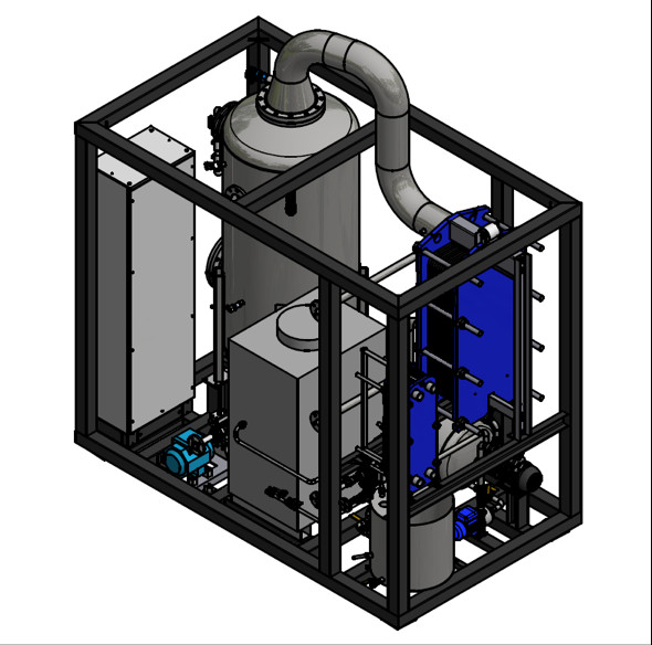
Parts of a vacuum evaporator
An industrial evaporator consists of several parts assembled in a robust mechanical construction that guarantees the control process and a level of automation that allows it to operate safely with minimal supervision and maintenance.
An industrial vacuum evaporator that treats wastewater includes a heat exchanger, valves, collectors, controls, pumps and a condenser. The most common designs are tanks with a jacket, tubular heat exchangers, plate and frame heat exchangers, and thin-film mixing evaporators.
The most important parts of an evaporator are described next.
1. Frame of the evaporator
These are usually built in the shape of a cylinder and can be installed vertically and horizontally.
Given their great mechanical resistance to internal pressure and depressurisation (vacuum), they are made with metal materials, usually austenitic stainless steel, although they are also built with other alloys (such as super deluxe stainless steels) or with coatings in materials like teflon, polyester, ebonite, etc.
A certain volume is designed for the inside to allow for the expansion of vapours.
The droplet separator is located at the top.
2. Vapour expansion chambers
3. Heat exchanger
There are different types of heat exchanger, built in varying materials with greater resistance to corrosion than stainless steel.
Immersed tube bundle
They may be liquid (heating fluid) / liquid (fluid to be heated) or steam (heating fluid) / liquid (fluid to be heated).
They are classified next and the characteristics of the most common versions are explained:
- Immersed in the liquid to be heated
- External, requiring a recirculating pump
- With a jacket (the evaporation frame has a heating jacket)
External pipe casing
The flow of heating fluid may be in parallel or against the current with regard to the liquid that is heated.
4. Demister (droplet separator)
5. Vapour condenser
6. Recirculating pump
7. Concentrate discharge pump
Installation of a vacuum evaporator
Despite each project having its own unique features requiring a personal analysis, there is a series of considerations that should be considered in all installation tasks in general:
Considerations according to the input water to be treatedr
Presence of solids in suspension
- Blocking of valves and pipes
- Premature fouling of heat exchangers
- Substances at the limit of solubility
- Possible solutions: Installation of filters
Presence of oils, hydrocarbons and similar substances
- Modification of the evaporation surface
- Poorer quality of distillate
- Fouling of heat exchangers and equipment
- Possible solutions: Installation of oil separator
Presence of volatile and/or non-condensable substances
- Low performance of the vacuum system
- Quality of the distillate
- Fouling of the distillate circuit
- Possible solutions: Stripping, post-treatment, etc.
Presence of encrusting substances:
- Blocking of valves and pipes
- Premature fouling of heat exchangers
- Possible solutions: Use of anti-encrusting systems or modification of pH
Presence of corrosive substances:
- Reduction in component useful life
- Increase in maintenance costs and time
- Possible solutions: Modification of pH, use of corrosion inhibitors
Presence of encrusting substances:
- Reduction in component useful life
- Increase in maintenance costs and time
- Possible solutions: Modification of pH, use of corrosion inhibitors
Considerations according to distances
The majority of evaporation equipment used are vacuum evaporators, meaning they have the capacity to vacuum themselves, but not in any condition.
Each technology works at different vacuum pressures and uses different vacuum systems, meaning this factor should be taken into account when deciding the distance/depth at which supply tanks should be positioned.
If the equipment is not a vacuum evaporator, it must always have a pressurised supply system. Equipment manuals usually specify these distances.

If the equipment does not have a distillate discharge pump, there are also restrictions on the back pressure in the distillate pipework:
- MVR equipment: 50 mbar
- LT equipment: 100 ÷ 300 mbar (depends on the technology)
- Thermal equipment: 100 ÷ 300 mbar (depends on the technology)
Equipment with a distillate discharge pump should have the pressure of the pump checked in consideration of the pressure it vacuums at.
The concentrate pipework must be configured such that it is as short as possible, with the minimum number of figures to facilitate its emptying. A good equipment set-up can avoid the following problems:
- Product pressure drop: Bearing in mind that the vacuum value can vary between -0.3 and -0.9 bar, the liquid to be treated should not exceed a pressure drop of 0.5 bar to ensure the equipment is supplied correctly.
- Distillate pressure drop: Bear in mind that the output pressure of the distillate is approximately 0.3 bar. This value, which is not high, involves a rather considerable pressure drop in the distillate transfer pipes.
- Pressure drop: The output pressure of the condensed product is equal to 0.7 bar. A check must be carried out on the pressure drops of the transfer line: carefully ensure the height of the pipework does not exceed 6 metres, and check all accessories and elbow joints are present.
If these phenomena cannot be avoided, the installation must be equipped with an intermediate tank with a booster pump. The condensed product outlet must be free, with no kind of restriction, and should never be immersed in the collection tank.
It is essential that at least 2.5 metres in free height be left above the equipment.
Considerations according to services available/required
All equipment we supply requires:
- Compressed air (normally 6 bar for instrumentation)
- Service water (normally 1.5 – 2.0 bar, filtered with low hardness)
- Electrical connection
MVR equipment may require:
- Exhaust air outlet
- Detergent tanks
- Demineralised cooling water is recommended
Thermal equipment also requires:
- Vapour or hot water at a maximum pressure (normally 1.5 – 3.0 bar)
- Cooling water or condensation systems
- Cold water to cool the vacuum pumps
Considerations according to environmental conditions
- The equipment cannot work in any pressure, temperature and/or humidity conditions. This must be taken into account when designing and installing the equipment.
- Equipment that must be installed outdoors and has not been designed for this form of installation must be protected by installing roofing, protective elements, etc.
- Installation areas must be sufficiently ventilated and the sun should not shine directly on sensitive zones of the equipment (HMI, screens, instruments, etc.).
- PVC deteriorates at a faster pace in the presence of UV radiation and extreme ambient temperature conditions.
- The equipment should not be installed in areas where corrosive products, radiation from heat sources, extremely cold zones, dust, and more, can be found.
- Consider raising parts located in areas prone to flooding.
- Do not assemble equipment in trenches, swimming pools, etc.
- Equipment with heat pump: maximum temperature of 35°C and minimum temperature of 10°C.
- MVR-FF equipment: maximum temperature of 40°C and minimum temperature of 5°C.
- In adiabatic equipment, the humidity and temperature may have a significant impact on production.
- Atmospheric pressure impacts the equipment’s production, meaning the elevation of the site where it is to be installed should be considered.
Maintenance of vacuum evaporators
Maintenance is the set of activities designed to maintain and/or re-establish the optimal conditions for use and operation of the components, including the scheduled replacement of parts and components subject to wear and tear with other original components, installed in accordance with the manufacturer's instructions.
Maintenance includes all improvement actions carried out on components and that do not alter the outlined conditions of use and operation.
This scope also includes other actions to adapt them to safety requirements, always according to the demands of local regulations in force or the manufacturer's regulations.
Before carrying out any maintenance tasks, the following actions must be completed:
- Always read the manual
- Pay attention to the hazard and/or warning signs
- Use suitable protective equipment
- Use tools suited to the task to be carried out
- Plan work
- Give notification about the work to be carried out
- Block equipment start-up when necessary
When carrying out maintenance work on the equipment and/or replacing a worn component, carefully observe the safety instructions set out by the owner (equipment user), as well as those indicated in the instruction manual (equipment manufacturer).
Corrective maintenance
This form of industrial maintenance consists of correcting the equipment's errors as they appear through use and wear. It may be planned, when this wear is anticipated and the industrial maintenance plan has already accounted for it. Alternatively, it may not be planned, when the defect occurs at an unexpected moment or sooner than expected.
Preventive maintenance
This involves a systematic action being carried out on the equipment, even though it has not shown signs of wear or errors. It considers the machinery and materials’ vulnerabilities and maintenance is planned at a suitable time so a serious repair will not come to pass. It requires a good industrial maintenance plan.
Predictive maintenance
This is one of the most necessary types of industrial maintenance in a correct industrial maintenance plan. It means the equipment is constantly being analysed to discern whether the machinery’s variables are changing and to predict breakdowns and errors before they occur.
To implement this type of industrial maintenance, the equipment must undergo certain measurements first. Some variables to be considered are vibration, energy consumption and temperature, among others. Once the normal parameters are known, variations may be calculated, indicating a possible issue with the equipment. Thus, a breakdown is prevented. This is one of the most advanced forms of industrial maintenance and it requires a greater information base, as well as knowledge of mathematics, physics, etc.
Zero hours or overhaul maintenance
This consists of tasks and procedures that leave the machine at zero hours of operation. This means that, either when the equipment's performance is beginning to drop or when it still works perfectly, all the necessary components are replaced and left as new. This is one of the forms of industrial maintenance that serves to ensure the equipment's useful life is lengthened in the long term in a controlled manner.
Maintenance in use
This is one of the types of industrial maintenance that requires the lowest amount of intervention. It is usually carried out by equipment users or personnel with low qualifications. It involves simple prevention tasks, as well as suitable cleaning or an observation of visible defects.
Most common maintenance in evaporation equipment
The most common maintenance tasks are:
- Filling tanks and reagents
- Cleaning heat exchangers
- Changing oil and greasing motors
- Replacing worn parts (mechanical closures, joins, etc.)
- Replacing or repairing broken down parts (motors, pumps, instruments, etc.)
A correct maintenance plan and strategy will translate to an increase in the equipment’s useful life as well as greater efficiency and better results.
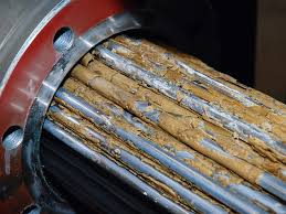
Encrustations and corrosion
The formation of encrustations is one of the worst enemies of evaporation equipment as they reduce or prevent the transfer of heat. They are caused by the formation of compounds with a low solubility that precipitate undesirably in the evaporator, especially where there is a great difference in temperature, meaning on the heat exchangers.
Calcium and magnesium salts, silica, minerals, etc. are some examples of substances that generally form encrustations.
They can be avoided with the correct pre-treatment of elimination with chemicals or by adding chelating and formulated anti-encrusting substances. In some cases, chemical or mechanical cleans must be carried out to remove encrustation deposits.
In evaporators, despite being made of stainless steel materials, the internal chemical corrosion of construction materials is a common phenomenon when brines or water containing chlorides, fluorides, certain acids, and more, are evaporated.
The conditions that strongly affect corrosion are:
- pH: corrosion increases with acidic pHs;
- Temperature: corrosion increases at higher temperatures;
- Presence of atmospheric oxygen.
</ul
There are two types of corrosion: uniform corrosion and pitting corrosion.
Uniform corrosion occurs in general in the form of weight loss owing to the dissolution of the metal or alloying in the solution. It is often frequent when acids are present.
Pitting corrosion appears in the form of holes, mainly in welded areas. It is caused by the presence of chlorides and fluorides and may even appear at alkaline pHs.
In both cases, the corrosion ends up destroying the materials in a short space of time.
Corrosion prevention is carried out via the appropriate selection of materials, avoiding acidic pHs, not exceeding the maximum concentration of chlorides at the working temperature, and, in some cases, cathodic protection via sacrificial cathodes (a metal less noble than that of the evaporator) may be useful.
Industrial vacuum crystallizers
Industrial vacuum crystallizers are an efficient, reliable and cost-effective technology for the treatment of highly polluted and complex effluents. At the same time, they offer great results in the recovery of raw materials and by-products from a wastewater stream.
The aim of crystallisation is to form a crystalline solid from the same melted matter or from its solution in a solvent; crystallisation can also be achieved from a vapour state without passing through the liquid state, but only in some cases. In the case of solutions, the crystallisation of solutes is achieved when a concentration higher than that of saturation is achieved, and this depends on the temperature and the nature of the solute and solvent. In the majority of cases, solubility decreases when the temperature drops and crystallisation can be achieved by cooling or evaporating the solvent, with both systems frequently being used in combination. When there is more than one component in the solution, the speed of diffusion plays an important role in the crystallisation process, along with the transfer of heat, while when there is only one component only heat transfer needs to be considered.
In any case, there is always a state of balance in which the liquid state and the solid state can be maintained without there being any apparent exchange of matter between them. This state is defined, in the case of pure matter, by their melting temperature, and in solutions and mixtures, by their saturation temperature or maximum solubility.
The growth of stable crystalline germs is possible at the expense of the molecules present in the oversaturated solution. The speed of growth, like in many change of state processes, can be considered directly proportional to a potential, and inversely proportional to a resistance.
The potential is the oversaturation of the solution and resistances can be considered broken down into two parts:
- Resistance to the diffusion of molecules until the crystal's surface is reached.
- Specific resistance of each face of the crystal, which depends on its orientation in relation to its crystal lattice.
Access of the dissolved molecules takes place via diffusion through a stationary layer surrounding the crystal. This phenomenon is what determines the speed of growth. The thickness of the transit layer must logically decrease, since the relative movement between the solid and liquid states is increased, and this speed increases when mixing occurs up to a certain point, after which it remains constant. The speed of growth does not increase further with oversaturation as the viscosity increases and the rate of diffusion decreases.
The separation of crystals from the rest of the system where they are produced is usually a complementary process, such as filtration, pressing or centrifuging.
The basic difference between evaporation and crystallisation is that the main goal of evaporation is the final concentration of a solution, while for crystallisation it is to produce and grow crystals.
Evaporation and crystallisation for zero discharge
Zero liquid discharge (ZLD) is a technique used to eliminate wastewater from industrial plants, replacing it with clean water that returns to the process, generating a minimal amount of solid waste that often includes by-products that may be sold or reused.
Zero liquid discharge systems are suitable for a wide range of industries, including energy generation, chemical product and fuel refinement, mining, distillation, food production and waste processing.
To treat the different flows of waste and processes, there is a wide variety of equipment available. However, this diversity is also one of the downsides of ZLD, as each system must be given a customised design, bearing in mind factors like contamination and the chemical products present in the water, the flow speed, the purity of the return water, etc.
Although each ZLD system is different, the majority consist of a pre-treatment phase, an evaporation phase to remove the majority of the water, and an additional concentration or crystallisation phase to obtain the final solid waste. The pre-treatment is usually focused on removing organic elements and any chemicals that may harm evaporation or other equipment in the facility. The most common water treatments, such as pH adjustment, flocculation, membrane treatment, degasification, oxidation, separation and even aerobic and anaerobic digestion, have been used as previous treatments for ZLD systems.
Traditionally, vapour-compression evaporation has been the main method used for ZLD processing, recovering around 95% of the wastewater as distillate. Any remaining concentrate is physically or chemically treated to generate solid waste (like crystals) and water, or via a crystallizer, when the product is to be recovered and it is economically viable. The evaporators used in ZLD systems usually operate at very low pressures to reduce the boiling point of the liquid being treated. This provides three benefits: less energy is consumed, thus reducing energy costs; the formation of many hydrates and salts occurs at very low concentrations and temperatures; lastly, the temperature of any concentrate remaining during subsequent processes can be raised.
Whatever the type of evaporator used, heat exchangers can play a crucial role in reducing the operating costs of a ZLD system by using heat from process water and other existing sources, and also be recapturing heat at the end of the process and reusing it to boost the general ZLD system's energy efficiency.
The basics of vacuum evaporation
Vacuum evaporation of liquids, as a physical process, is based on the particular aspect of transferring heat between two pieces of matter with a different temperature: the liquid to be heated that is colder and the heating fluid (or matter) that is hotter.
Evaporation is used to separate a part of the liquid contained in a solution or suspension.
When it is done by boiling, it is called isothermal evaporation (Fig. 1 A,B). As defined by Boyle’s law, when it is an adiabatic process, also known as isentropic evaporation (Fig. 2 A,B), the entropy of the system remains constant.
The liquid to be evaporated (water), which is previously heated, must be cooled by ceding work to the medium, generally air that is humidified, via its own evaporation as it changes to the vapour state. This system is widely used in industrial cooling systems with evaporation towers.
In both cases, the heat needed to heat the water can come from any heating means: generation of hot water or vapour, heat pump, use of residual heat, etc.
The evaporation surface has a fixed value in a pre-existing evaporator. The same cannot be said of the difference in temperature between the condensing vapour and the liquid to be evaporated.
This factor is a direct function of the temperatures in the condensation chamber and the evaporation chamber. The heat in the condensation chamber depends on the vapour pressure, which is kept constant in a normal facility.
Only when non-condensing gases are accumulated can the condensation temperature drop to the same total pressure, as this will be the sum of the vapour pressure and the pressure the non-condensing gases exercise.
In a piece of apparatus that is evaporating water, the temperature of the evaporation chamber is the boiling point of the pressurised water supplied. This is determined using a manometer.
The temperature can be found in the vapour tables. In practice, the solution that is evaporated has a greater or smaller proportion of dissolved solids, for which reason its boiling point is higher than that of water at the same pressure.
In general, evaporators work continuously, thus the concentration of the liquid may be considered constant and equal to the output concentration. For the purpose of heat transfer, it is supposed that the liquid is heated to boiling point before reaching the heating surface.
The speed of heat transfer through a solid body (heat exchanger) is defined by Fourier's law and basically depends on the difference in temperature between the heating centre and the liquid to be evaporated, the exchange area and the thermal conductivity of the exchanger’s solid material.
The heat transfer speed basically depends on the following factors:
a) Difference in temperature between the heating centre and the liquid to be evaporated (Δ𝑇)
The boiling point of the liquid to be evaporated increases as it becomes more concentrated. However, by operating in vacuum conditions, the difference in temperature between the heating agent and the liquid to be evaporator increases, as the boiling point of the mixture is far lower than the atmospheric pressure temperature. The greater the difference in temperature, the faster the speed of evaporation.
b) Exchange area (𝐴)
The effective exchange area depends on the geometry of the equipment and phenomena inherent to the concentration of the solution, as is the case of the depositing of solids or encrustations on the exchange surface. The larger the area, the greater the capacity for heat exchange and the faster the speed of evaporation.
c) Thermal conductivity of the solid material of heat transfer (𝑘)
This is a physical property of solid materials that measures their capacity to conduct heat, for example, that of stainless steel is 52 𝑊/𝑚𝐾, and that of aluminium is 237 𝑊/𝑚𝐾.
d) Thermal transmittance (𝑈)
Thermal transmittance (or the overall heat transfer coefficient) depends on the physical properties of the fluids involved (heating agent and liquid to be evaporated), the material of the wall on which heat is exchanged, the equipment's design and geometry, as well as the flow parameters (speeds of fluid circulation, etc.).
The larger this coefficient, the easier it is for the equipment to exchange heat. This is expressed via the following equation:
𝑞 = 𝑈 𝐴 ∆𝑇
Where 𝑞 is the flow of heat, 𝑈 is the heat transfer coefficient, 𝐴 is the available exchange
area and ∆ 𝑇 is the difference in temperature.
e) Concentration factor/evaporation ratio (𝐹𝐶)
If an input solution A, formed by an evaporating solvent (or distillate) D (e.g. water) and a concentrate B, the ratio between the volumetric flows can be expressed as:
𝑚𝐴 = ሶ 𝑚𝐷 + ሶ 𝑚𝐵
The concentration factor 𝐹𝐶 is defined as the ratio between input flow and concentrate flow:
𝐹𝐶 = ሶ 𝑚𝐴
ሶ
𝑚𝐵
In terms of concentration, the concentration factor is expressed as follows:
𝐹𝐶 = 𝑐𝐵
Known as the design concentration factor 𝐹𝐶, the distillate flows and concentrate flows can be discerned via the following expressions:
ሶ
𝑚𝐷 = 𝐹𝐶−1
𝐹𝐶 ሶ 𝑚𝐴 ሶ 𝑚𝐵 = 1
𝐹𝐶 ሶ
Properties of the liquid to be evaporated
The increase in the boiling point (ΔTb) is the difference in temperature between the boiling point of the pure solvent (water) and the boiling point of the solution at a given concentration (morality).
During evaporation of a solution, the concentration increases and, therefore, the molality, resulting in an increase in boiling point.
To determine this increase, the following expression can be used:
Δ𝑇𝑏 = 𝑖 𝐾𝑏 𝑎
Where 𝑖 is the van’t Hoff factor (for sugar in water it is 1, for sodium chloride in water it is 2, for calcium chloride it is 3, for hydrochloric acid in water it is 2), 𝐾𝑏 is the boiling-point elevation constant of the solution (for water it is 0.52 K) and 𝑎 is the chemical activity.
The chemical activity is determined as:
𝑎𝑖 = 𝛾𝑖 𝑥𝑖
Where 𝑎𝑖 is the chemical activity of the species 𝑖, 𝛾𝑖 is the activity coefficient of the species 𝑖 and 𝑥𝑖 is the mole fraction of the species 𝑖.
Another method used to determine the boiling point of an aqueous solution (𝑇𝑏) is Dühring's rule.
The boiling point of an aqueous solution at different pressures is a linear function of the boiling point of water at the same pressure.
Thus, if the boiling point at two different pressures is known, a diagram can be drawn to obtain the boiling point at any pressure.
Boiling-point elevation varies little with pressure and is almost constant within the interval that may be of interest. Once the elevation value is known, it can be added to the temperature deduced from the indications of the gauge pressure and the vapour tables, and thus the true boiling point can be found.
For concentrated solutions, the correction term may be the same order of magnitude as the real difference in temperature.
Density (𝜌) and viscosity (𝜇) of the liquid that is being evaporated:
- In aqueous solutions of salts, their density tends to increase although their viscosity barely does.
- In mixtures of water with polymers (or organic substances), their initial density is almost unchanged, but their viscosity increases considerably.
The temperature of the liquid directly affects these two parameters such that, at a high temperature, the density and viscosity decrease, and when cooled, they increase to the point that discharge via pumps may not be viable.
The formation of foam during boiling, especially in vacuum evaporation, is due to the formation of gas bubbles trapped in small liquid droplets. They mainly occur when boiling foaming liquids, generally when they contain surfactants or soaps. It can also be aggravated by the forced circulation of the liquid. The formation of foam must be controlled by anti-foaming agents or a specific design to break the foam, otherwise there is a risk that it will be dragged by the vapour or move into the condensation chamber, contaminating the distilled water.
Some liquids are heat-sensitive, meaning above certain temperatures they may decompose or vary their properties (natural extracts, drugs, food additives, etc.). In these cases, a low-temperature evaporation system must be selected.
Basic calculations in an evaporation system
The most important parameters for the correct design of an evaporation system are the heat transmission coefficient and the surface necessary to carry out the process.
Heat transfer coefficient
The amount of heat transferred in an evaporator is defined by the equation Q = U*A(T-T’). In it, U depends on the design and method of operation in the evaporator.
Overall resistance, considering as such the inverse of the overall coefficient, is comprised of five resistances in series: a) resistance of the condensing vapour film; b) resistance of the crust formed on the surface of the heating element in contact with the vapour; c) resistance of the heating element's wall; d) resistance of the crust formed on the surface of the heating element in contact with the boiling liquid; e) resistance of the boiling liquid's film.
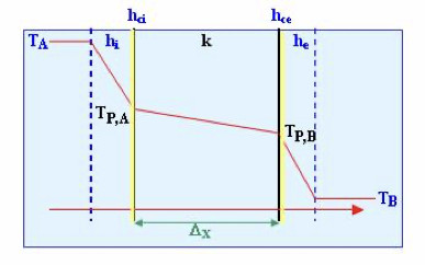
Thus, the overall heat transfer coefficient based on the internal area of the heating element is:

Where Ai is the internal area; Ae, the external area; hci and hce, the internal and external crust coefficients, respectively; k the metal wall's conductive heat transfer coefficient; and hi and he, the convective heat transfer coefficients (film coefficients), internal and external, respectively.
1. Film coefficient of the condensing vapour: (he). This coefficient is high even in the case of condensation in film. If the condensation is produced in droplets, it is even greater. It can be taken as an approximate value of the presence of non-condensing gases, reducing the value of this coefficient.
2. Coefficients of the crusts: (hci, hce). These coefficients are generally high and difficult to quantify. Thus, the resistance due to the same is not considered when doing calculations, especially in cases in which a high speed of circulation reduces the formation of encrustations. For normal operation and cleaning, the crust coefficients have approximate values between 0.58 and
3. Coefficient of the metal wall: (k). The metal wall generally has a high conductive heat transfer coefficient and, therefore, the wall's thermal resistance, unless it is very thick, is negligible.
4. Film coefficient of the boiling liquid: (hi). This coefficient is the most influential and depends on: a) the speed of the liquid on the heating surface; b) the viscosity of the boiling liquid; c) the cleanliness of the heating surface. The circulation speed depends on whether convection is natural or forced via mixing, and the geometry of the heating surface with regard to the shape and dimensions of the evaporation area. In the majority of evaporators, and especially in those that operate with viscous liquids, the overall heat transfer coefficient mainly depends on this film coefficient.
In general, given the difficulties presented in determining individual coefficients, experimental data refer to overall coefficients, the values of which mainly depend on the value of the film coefficient of the boiling liquid.
The bibliography includes tables and graphic representations for the values of U in the different types of evaporators in normal operating conditions.
Calculation of the exchange area required for evaporation
Mass and energy balances must be considered. For the case of an evaporator powered with a stream F and where two streams are extracted, that of concentrate S and that of distillate E, such as the figure:
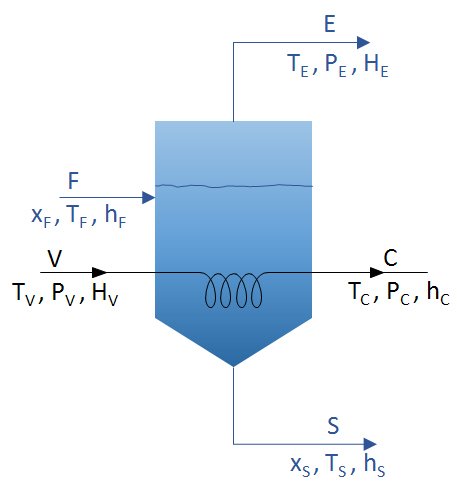
The diagram presents the parameters to be considered in vacuum evaporation. These mass and energy balances can be considered:
Overall mass balance
F=E+S
V = C
Mass balance for the solute
F x F = S x S
Energy balances
VHV+F*hF=C*hC+(E*HE)+(S*hS)
Q = V HV – C hC = V (HV – hC) = U A ΔT
- Q: flow of heat transferred via the heating surface of the evaporator.
- U: the overall heat transfer coefficient.
- A: the area necessary for evaporation.
- ΔT: the difference in temperature between the heating agent and the liquid to be evaporated.
Example of energy saving calculation of an evaporator operating with a vacuum
For the purpose of checking the energy-saving benefit involved in using vacuum evaporators, the following example is given:
If we want to evaporate 1000 kg/h of water at 20⁰C and we use a piece of vacuum equipment (boiling point = 60⁰C) and another piece of atmospheric equipment (boiling point = 100⁰C), what would be the energy savings?
- The energy required to take the water from 20⁰C to 60⁰C will be Q = mCe(Tf-To) = 1000 kg/h x 1 kcal/kg⁰C x (60⁰C-20⁰C)= 40000 kcal/h
- The energy required to take the water from 20⁰C to 100⁰C will be Q = mCe(Tf-To) = 1000 kg/h x 1 kcal/kg⁰C x (100⁰C-20⁰C)= 80000 kcal/h
- The energy required to change the state of the 2000 kg of water will be Q = mCL = 1000 kg x539 kcal/kg = 539000 kcal
- At a reduced pressure, the energy necessary will be 539000 + 40000 kcal/h = 579000 kcal/h
- At atmospheric pressure, the energy necessary will be 539000 + 80000 kcal/h = 619000 kcal/h
- The energy saving is 40000 kcal/h
- In terms of percentage, the saving will be 6.5%.
- Furthermore, the energy consumed for heating is only around 10% of the total; the remainder (around 90%) is for the change of state.
As can be observed, current evaporation techniques are aimed at recovering latent heat from the distilled vapour.
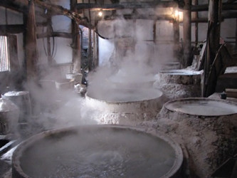
Brief history of industrial evaporation
The use of rudimentary apparatus to boil water to concentrate a solute is as old as the history of mankind. During the neolithic period and, above all, at the end of the Bronze Age, the most important application was to produce salt in places that were far from the sea using the system named briquettes.
They were built in ceramics, filled with salt water from lakes and brackish springs, and boiled until fully evaporated, then the briquette was broken and precious salt was obtained.
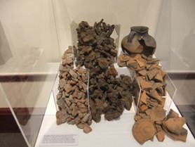
In antiquity, in China it was produced using this procedure, and in Europe it was used since the time of Ancient Rome until well into the 19th century.
The first scientist to study and explain the process of evaporation was the Swede, Nils Wallerius (Stora Mellosa 1706 – Uppsala 1764), a physicist and theologian, and member of the Royal Swedish Academy of Sciences in 1739.

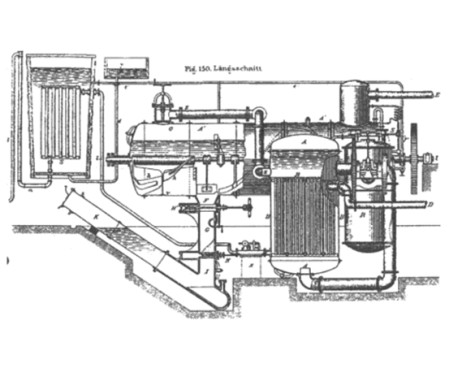
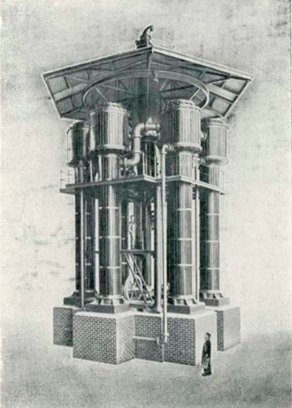
Between 1876 and 1877, the engineer Paul Piccard developed some evaporator prototypes that were very similar to the systems used nowadays, and they sparked great admiration at the Exposition Universelle of 1878.
In the 19th century, the demand for sugar brought about the development of ingenious sugar refineries that used evaporation to concentrate and crystallise sugar.
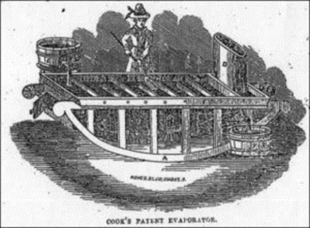
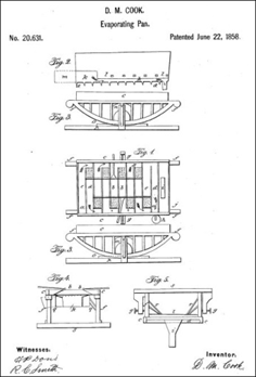
Another procedure developed in 1858 was the system patented by D. M. Cook. It was the first industrial evaporator, using trays, and was patented for the production of sugar before being marketed after 1860.
Freshwater production using evaporators
In 1884, the first water evaporators appeared, to be used in ships and marine settings to produce freshwater from saltwater, harnessing the vapour from ship boilers.
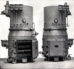
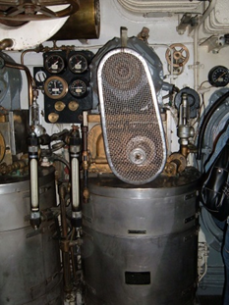
The year 1941 brought about the emergence of vapour-compression technology to produce freshwater in submarines, especially during the long periods of immersion when diesel motors were not operating and they needed to work with electricity from batteries.
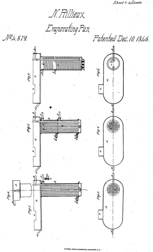
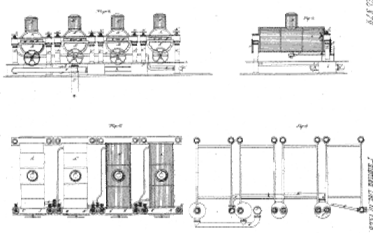
The French-American engineer Norbert Rillieux (1806 – 1894) was the inventor and pioneer of multiple-effect evaporation, which represented a great step forward in the sugar industry.
In 1899, Paul Kestner developed a new evaporation technology with the falling film system, and in 1908, Willheim Wiegand patented a multiple-effect evaporator with liquid circulation.

The 20th century and the development of industrial evaporators
In 1940, the company Aqua-Chem, a division of Cleaver-Brooks Co., won a contract to manufacture water evaporators to produce potable water for the American armed forces during World War II and the Korean War.
This industrial development brought about numerous advances that would be subsequently used to design large desalination plants via the technique of multiple-effect flash evaporator.
The 21st century advancement of the technique towards the circular economy
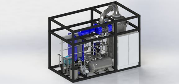
In 2015, Condorchem Envitech developed the MVR evaporator with forced circulation at a low temperature and minimal electrical consumption.
In 2017, Condorchem Envitech designed and built the first adiabatic concentrator that did not require a heat supply, making use of the temperature of the concentrate discharge from the MEE evaporator.