Treating liquid effluent via evaporation has always been a highly effective, robust and simple method compared to other more conventional treatment systems. The fact that evaporation-based systems require greater energy consumption has meant that they are reserved for those cases in which conventional systems are ineffective, as is the case of brine treatment, leachate from MSW landfill, oily waters, etc., or when it is intended to avoid the discharge of the treated effluent (zero discharge).
Nevertheless, the development of increasingly sustainable, and above all, more economical energy generation processes makes the evaporation processes applied to the treatment of effluents an unbeatable choice thanks to their effectiveness, crossover appeal and simplicity.
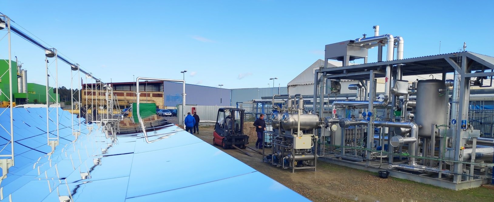
WASTEWATER TREATMENT EVAPORATORS POWERED BY SOLAR ENERGY
In this regard, solar energy has great potential. Although this energy source is generally associated with the use of solar panels for direct conversion of solar radiation into electricity, there is a technology that exploits solar energy with a much greater yield: thermosolar energy. A thermosolar plant transforms the solar radiation it receives into thermal energy, which can be used directly in industrial processes that require heat, or also indirectly as an energy source of a conventional thermodynamic cycle to generate electricity.
To obtain thermal energy in a thermosolar plant, optical devices are used (lenses or mirrors) to capture and concentrate the solar radiation on a device called a receptor. Simultaneously, a fluid is made to circulate through the receptor, which heats up due to the high radiation flow, and then it is passed through a heat exchanger, yielding the thermal energy produced. Usually, in heat applications in industrial processes, solar concentrators operate in a range of temperatures between 150 and 200 ºC.
To maximize the absorption of the solar radiation and minimize the losses due to emission or convection, several technologies have been developed. Although the systems that produce a higher yield are constructed with cylinder-parabolic collectors (CCPs), in recent years the use of systems that use flat segmented mirrors according to the Fresnel approach (Linear Fresnel Reflector – LFR) has grown in popularity. These systems, at the cost of a loss of a certain amount of concentration an effectiveness, nevertheless score points for simplicity, which means a reduction in costs.
Normally, an LFR consists of a set of flat mirrors and a linear receptor, which is positioned in the focal line of the optical arrangement constructed with the lines of the mirrors. Generally, a back-up concentration system is used on the focal line to maximize the solar concentration and thus obtain a flow of radiation in the receptor that is much greater. Thus, for the supply of thermal energy to an evaporator, taking into account the operating conditions required to maximize the efficiency of the process, RFL technology is the optimum choice on account of its excellent use of the site, working temperatures, its simplicity of construction and its competitive costs. Although it is true that a vacuum evaporator can operate satisfactorily with a heating fluid that is at 90° C, using RFL technology it is possible to achieve 120° C relatively simply, so, by having a higher temperature leap, it is possible to work with multi-effect equipment (4 or 5 stages or effects), increasing the overall performance achieved very significantly.
Another aspect that must be taken into account due to its importance for the viability of this technology is the degree to which the temporal production profile (daily, monthly and annual) matches the demand curve. A greater and better use of solar energy is only possible when the consumption profiles coincide with the energy production curves of the installation. Thus, the evaporation systems that can work continuously in the treatment of effluents that have been previously stored vastly optimize the use of solar resources. However, it is not strictly necessary to store the effluent to be treated in order to maximize the yield. In addition, as a complement, it is also possible to store thermal energy, which allows hours of production to be extended, even when solar radiation is not available. There are different technologies to utilize the surplus thermal energy produced, although the most highly developed and widely used approach is the use of molten salts. In these systems, a heat-carrying fluid heated by solar radiation transfers its energy in a heat exchanger to a stream of molten salts. Thus, during the loading cycle of the storage system, the molten salts are pumped from the salt tank at a lower temperature through a heat exchanger to the salt tank at a higher temperature. And vice versa when the previously stored energy is consumed.
In many cases, depending on the plant’s location, the solar radiation available throughout the year is insufficient to meet the demand for production. In these cases, it is necessary to complement the system with another energy source in order to be able to boost the production to whatever is necessary to meet the demand. This is not a problem since one of the advantages of solar thermal plants is their ease of hybridization with other sources of energy, preferably renewable or, failing that, from the consumption of fossil fuels. In the latter case, although it will not be a zero-emissions plant, they will have been minimized to the utmost.
In this regard, for evaporation applications in which one aims to maximize the sustainability of the process, solar thermal energy is an especially appropriate source of energy since it is renewable, inexhaustible and easily managed by hybridizing it with other fuel (biogas, biomass or fossil fuels); furthermore, it is possible to store the sun’s heat for later use.
ADVANTATGES OF SOLARVAP® SYSTEM
Thus, the SOLARVAP® system harnesses the most advanced technology at the service of sustainability, since evaporation systems based on membrane distillation combined with solar thermal plants have several very valuable advantages, which is why they have such great potential. Among the main advantages are the following:
- SUSTAINABLE, thanks to the use of a renewable and inexhaustible source of energy.
- ECOLOGICAL, thanks to the minimization and, in some cases, zero emission of greenhouse gases.
- CROSS-OVER CAPABILITY, because it is easy to hybridize this technology with the consumption of other energy sources (biomass, biogas, etc.).
- ADAPTABLE, because evaporation by means of membrane distillation delivers high performance with a very wide variety of different liquid effluents.
- GLOBAL, because it can be implanted anywhere in the world where solar radiation is sufficient.
- ECONOMICAL, as it achieves very low operating costs while the CAPEX is also reasonably low.
The SOLARVAP® system, the result of a joint development by the companies Condorchem Envitech and Rioglass Solar, both with a vast experience and a long list of success stories and testimonials worldwide in each sector, brings together all these characteristics and is one of the most technologically advances options available as well as by far the most economical.
