
Sections
What is a filtration membrane?
Membranes are semipermeable physical barriers that separate two phases, preventing their intimate contact and selectively restricting the movement of molecules through it.
This fact allows for the separation of contaminating substances from water, generating a purified aqueous effluent.
The rapid expansion, starting from 1960, of the use of membranes in industrial-scale separation processes has been facilitated by two facts: the manufacturing of membranes capable of providing high permeate flows and the production of compact, inexpensive, and easily interchangeable devices that can accommodate large membrane surfaces.
The main characteristics of membrane separation processes are as follows:
- They allow the separation of contaminants that are dissolved or dispersed in colloidal form.
- They eliminate contaminants that are present at low concentrations.
- Operations are carried out at room temperature.
- Simple processes and compact designs that occupy little space.
- They can be combined with other treatments.
- They do not actually eliminate the contaminant, they only concentrate it in another phase.
- There may be incompatibilities between the contaminant and the membrane.
- Membrane fouling issues: the need for other substances to carry out cleaning, pH adjustments, downtime cycles for equipment cleaning.
- Poor scaling: double flow-double equipment (modular equipment).
- Noise generated by the equipment necessary to achieve high pressures.
Types of membrane
Membranes can be made from polymeric, ceramic, or metallic materials.
Based on their physical structure, they can be classified into:
Microporous membranes
Porous structures with a narrow pore size distribution. Membranes that fall into this group have a pore diameter distribution of 0.001mm – 10mm.
The water purification processes that use these membranes, microfiltration and ultrafiltration, are based on preventing the passage through the membrane of those contaminants larger than the largest pore diameter of the membrane by exclusion, with substances whose size falls between the largest and smallest pore diameters being partially rejected. In this type of membrane, the driving force responsible for the permeate flow through the membrane is a pressure difference.
Deep filters act by retaining contaminants inside them, either by adsorption on the walls of the pores or by capturing them in the constrictions of the pore channels. They are isotropic membranes and are commonly used in microfiltration.
Screen-type filters are membranes with a narrow pore size distribution. They capture and accumulate on their surface the contaminants larger than the pores.
Substances smaller than the pore size that pass through the membrane are not retained inside but exit as part of the permeate. They are usually anisotropic membranes and are used in ultrafiltration.
Dense membranes
Structures without pores where the passage of substances through the membrane follows a solution-diffusion model, in which the components of the solution dissolve in the membrane and then diffuse through it.
The different solubility and diffusivity of the solution components in the membrane allow for the separation of substances the size of molecules and ions. Due to the high pressures at which these processes occur, the membranes are of the anisotropic type.
Reverse osmosis and nanofiltration are processes that use this type of membrane.
Electrically charged membranes
They can be porous or dense, with fixed anionic or cationic residues in the membrane structure. The separation is a consequence of the membrane’s charge, excluding those components whose charge is the same as that of the membrane.
The separation also depends on the charge and concentration of the ions in the solution: monovalent ions are excluded less effectively than divalent ones; likewise, the separation process is less effective in solutions of high ionic strength.
These membranes are used in electrodialysis processes.
Anisotropic membranes
Anisotropic membranes are laminar or tubular structures where the pore size, porosity, or composition of the membrane changes along its thickness.
They consist of a thin film (dense or with very fine pores) supported on a thicker and more porous layer, such that the first is responsible for the separation process and the second provides the system with sufficient mechanical strength to withstand working conditions.
The film responsible for the separation process and the one providing mechanical strength can be made from the same material (Loeb-Sourirajan membranes) or from different materials (composite membranes).
Since the rate of passage of substances through the membrane is inversely proportional to its thickness, membranes should be as thin as possible.
By manufacturing anisotropic (asymmetric) membranes, it is possible to achieve membrane thicknesses of less than 20 mm, which are the thicknesses of conventional membranes (isotropic or symmetric).
The improvement in separation processes due to this type of membrane has made them the choice in industrial-scale processes.
Membrane configurations
Membranes can be manufactured in the form of flat, tubular sheets or of the type known as hollow fiber.
Hollow fibers are tubular structures with an external diameter of 0.1-1.0 mm and an internal diameter of 50 mm, dimensions that are an order of magnitude smaller than those of tubular membranes.
Most of them are of the anisotropic type, where the structure responsible for separation is located on the outer or inner surface of the fiber.
Hollow fibers are arranged in compact modules with a greater filtering surface than flat sheet and tubular membrane modules, allowing for more efficient separations.
The development of materials for the manufacture of membranes that allow for efficient separations and their arrangement in configurations or modules that are easy to install and replace, which can be grouped to achieve filtering surfaces of hundreds or thousands of m2 while occupying acceptable volumes, has been the key to the use of membranes on an industrial scale.
Currently, the configurations in which membranes are presented are referred to as:
Membrane cartridges
Where the membranes, suitably folded, are wound around the permeate collector, packed in a housing of 25 cm in length and 6 cm in diameter, arranged in line with the flow to be treated (feed), with contaminants retained in the membrane and generating a purified effluent (permeate).
In these arrangements, surface developments of around 0.3 m2 are achieved. Membrane cartridges are disposable.
Plate-frame modules
They have a similar arrangement to filter presses. The membranes are arranged in frames separated by plates.
The feed, driven by a pump, circulates through the plate-membrane spaces, concentrating contaminants as the permeate flow occurs through the walls of the membranes.
Tubular membrane modules
Consisting of cylindrical housings that contain a variable number of tubular membranes, the feed is pumped through the interior of the membranes, producing a lateral flow of permeate through the walls.
The housing has the appropriate devices to collect the permeate and concentrate flows.
Tubular membranes are made up of a porous support of paper or fiberglass on which the filtering surface is deposited. They are also constructed from ceramic materials.
Tubular modules usually have lengths of 13 cm – 20 cm, with 4 – 6 membranes of 0.5 cm – 1 cm in diameter arranged inside. The circulation speed of the feed inside the membranes is 2 m/s – 6 m/s, resulting in pressure losses of 14 – 21 kPa per module.
The energy consumption of plants using this type of module is on the order of 0.8 – 2.5 kWh/100 L of permeate.
Spiral-wound membrane modules
Complex structure where a membrane in the form of a “flat bag,” with an internal separator from the membrane walls, is spirally wound around the permeate collector tube, connecting to it through the open part of the “bag.”
The outer walls of the membrane, which form the spirals, are separated by hollow structures that allow the feed to flow through them and the permeate to flow laterally through the walls of the membranes.
These modules usually have a diameter of 20 cm and a length of 100 cm with several wound membranes providing a membrane surface of 1–2 m2.
Hollow fiber membrane modules
Structures similar to multitubular heat exchangers, 70 cm long and 8 cm in diameter, housing 500 – 2000 hollow fiber membranes.
There are basically two configurations, depending on whether the feed circulates inside or outside the fibers. The pressure drop in this type of module is from 0.7 bar to 70 bar, depending on the type of application.
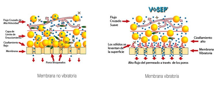
Vibrating membrane modules VR
To address the common problem of membrane technologies, the clogging caused by layers of residues that accumulate on their surface, vibrating membranes VR have been developed.
The significant difference compared to traditional membranes is that the basic design is vertical instead of horizontal, so the space required per unit is less than in other separation systems.
These membranes can filter any type of wastewater and allow for the treatment of effluents with a high solid load. It is also a technology that does not require chemicals to operate, except for those necessary for the periodic cleaning of the membrane.
In a VR System, the liquid to be treated is practically stationary, slowly circulating between the parallel membrane elements. The cleaning action of the shear is created by vigorously vibrating the membrane elements in a direction tangential to the surface of the membranes.
 Credit: VSEP
The shear waves produced by the vibration of the membrane lift the solids from the surface of the membrane and remix them with the material or effluent moving inside the membrane. This intense shear allows the pores of the membrane to be cleaner, achieving a higher performance than conventional membranes.
Vibrating membranes VR allow for the recovery of around 90% of the treated water as clean water that can be discharged or reused.
The type of membrane used in VR Systems varies depending on the effluent to be treated. A very general classification would be as follows:
- Reverse Osmosis membranes for the separation of materials.
- Nanofiltration membranes for wastewater treatment and concentration.
- Ultrafiltration membranes for oily separations and concentration.
- Microfiltration membranes for separating larger particles from a liquid phase.
Other important parameters are pressure, temperature, vibration amplitude, and the residence time of the material inside the membrane.
All these parameters are optimized during initial tests and then recorded in a PLC that automatically controls the system.
Additionally, it is a modular system that can be modified after installation if necessary:
- It can be easily added to an existing system to improve performance.
- It can be installed in areas where space is a limitation.
- It is easy to transport and can be moved from one plant to another.
- It can be installed in multiple systems or phases as a single step.
- More units can be installed as production increases.
