Sections
- Introduction
- Frontal filtration and Tangential filtration
- Ceramic membrane features
- Scope of application
- Recovery of filtrates and concentrates
- Ceramic membrane installation calculation
Introduction
Current trends in water treatment are oriented towards the use of membranes, either to filter suspended particles, colloids, organic material, bacteria, macromolecules and even salts; thus, we cover the separation spectrum according to the size and nature of the pollutants.
Basically, the membranes are classified into organic and inorganic. The former are usually used for lightly polluted water, as the materials they are made of (e.g. polysulfone, polyamide or cellulose) do not tolerate high concentrations of pollutants or extreme pH or temperature values. In addition, oxidants, oils and organic matter are undesirable agents to be avoided due to them fouling and deteriorating the membranes.
Inorganic membranes are required for the treatment of complex effluents, and increasingly we observe ceramic ones being used on the market, because of their high efficiency, durability and resistance to the most extreme media.
To determine the ceramic membrane to be used in a specific case, the nature of the effluent to be treated and the size of the particles to be separated must be taken into account. This establishes the so-called cut-off and the membrane pore size units.
Measurement units and relationship between them
The main units used to measure particle size are:
- Micron (µm) = 10-3mm
- Nanometre (nm)= 10-3µm
- Armstrong (A0) = 10-4µm
The filtration ranges based on the membrane pore size are classified as: Microfiltration, Ultrafiltration and Nanofiltration, although nanofiltration includes the partial separation of the larger salts with a limit close to reverse osmosis.
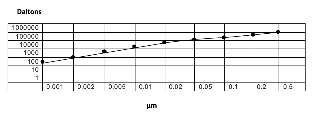
The particle size unit used in Microfiltration is the μm, while for Ultrafiltration and Nanofiltration it is the kDa (kilodalton), defined as the molecular mass unit equivalent to 1,000 daltons. One dalton is one tenth of the mass of the carbon atom and is equal to 1.66 X 10⁻²⁴ g.
Thus, for these levels, an approximate relationship between particle size and molecular mass is established, according to the following graph:
 In reverse osmosis, salt separation and other more complex electrochemical phenomena are involved. The separation is said to be at a molecular level using A0 and the molecular type. This study does not discuss reverse osmosis membranes, as we focus the application towards the treatment of effluents, for which these membranes have many limitations, as indicated at the beginning of the text.
Ceramic membrane manufacturers establish 3 groups of filtration types, according to their manufactured range:
- Microfiltration: 0.1-1.4 µm
- Ultrafiltration: 15-300 kDa
- Nanofiltration: 1-10 kDa
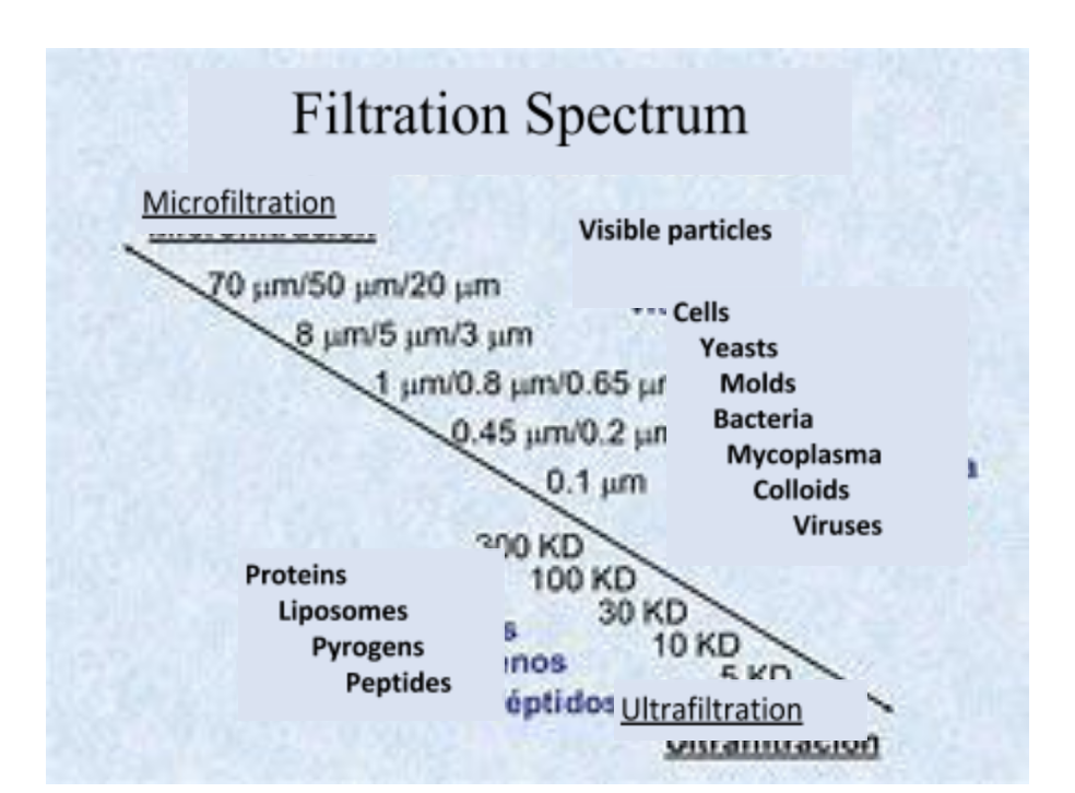
The following graph shows the filtration spectrum for ultra- and microfiltration, with some of the contaminants usually separated at each level.
Frontal filtration and Tangential filtration
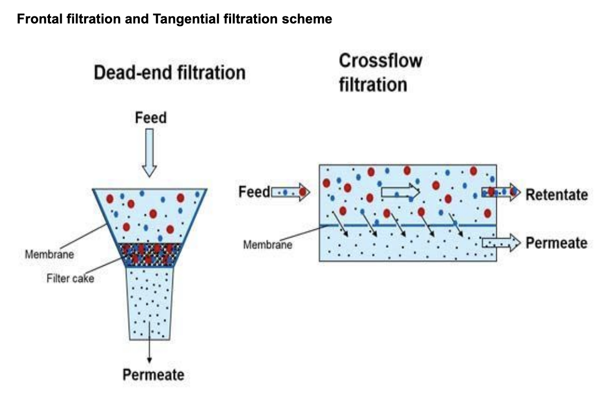
When a frontal or total filtration is performed, all the liquid that comes into contact with the surface of the membrane is forced to pass through it. Some solids and components will be retained by the membrane while the rest will pass through to the other side. This process depends mainly on the pore size of the membrane, although there are other factors to take into account. Consequently, the liquid will gradually experience a greater resistance to passing through the membrane, due to the accumulation of substances. When the pressure of the incoming fluid remains continuous, the flow will be reduced until it has decreased so much that the membrane will have to be cleaned, since the retained layer (concentrate) will be too thick. The pressure required to pass the flow through the membrane is called the Transmembrane Pressure (TMP).
The TMP is defined as the membrane pressure gradient or the mean inflow pressure minus the permeate or filtrate pressure. As the filter surface becomes clogged, this parameter has to increase if the process is to continue functioning adequately, until it reaches a limit at which the cleaning process should be started. This means that the filtration process is considered as discontinuous, while ensuring that the operating cycle is as long as possible and the cleaning quick and effective. Therefore, this type of filtration has certain drawbacks, but may be a good solution for many applications, such as for concentrating components.
In ceramic membranes, tangential filtration is carried out. Here, the retentate or concentrate is recirculated and becomes part of the supply flow parallel to the membrane through a feedback cycle. Thus, this type of filtration has working pressure ranges much lower than those of total filtration. Only a small part of the flow will cross the membrane and become permeate (filtered), with most going to the concentrate tank.
The water flow speed parallel to the membrane is relatively high. The purpose of this flow is to control the thickness of the layer. As a consequence of the speed at which the water moves, the flow forces are high, which carries away the suspended solids as the liquid circulates.
The chance of clogging in this filtration system is reduced and the formation of the solid film is delayed and reduced. Tangential filtration management can achieve stable flows. However, contamination still occurs and the membranes have to be cleaned, which, in the case of ceramics, involves temperature values Oxidants, solvents and extreme pH.
The Linear velocity (VL) or tangential flow is the feed flow within the membrane. For a tubular membrane, the linear velocity can be defined as the ratio between the inflow and the inner section of the membrane.
VL= Fr/ Si in (m/sg.)
Where: Fr is the feed flow [m3/s] and Si is the inner section of the membrane [m2] [m2]
The higher the linear velocity, the more deposited material is removed and, consequently, the lower the hydraulic resistance across the membrane leading to more permeate flow. Higher feed rates also reduce the polarization phenomena of the concentration by increasing the mass transfer coefficient.
Ceramic membrane features
Ceramic membranes are mainly manufactured with tabular alumina (αAl 2O3) and silicon carbide (SiC) at high sintering temperatures (1,800-2,000ºC).
Although there are also flat membrane models for specific applications, these membranes usually have a tubular shape and different configurations according to the number of channels within them. Thus, for loaded or higher viscosity effluents, a smaller number of membranes with large channels are usually used; while, for more fluid and less loaded effluents, membranes with more, smaller size channels are used. Membranes with more channels have a larger equivalent filtration surface. The most reliable way to design the facility to be implemented is to perform pilot studies or trials with the liquid to be treated, and to test different membranes of probable use.
The set of membranes to carry out the treatment is housed inside protective stainless steel covers with elastomer joints suitable for the media and for cleaning (usually Viton or PTFE).
Covers for ceramic membranes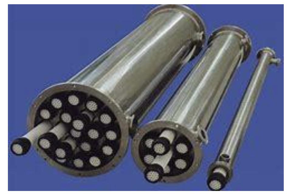
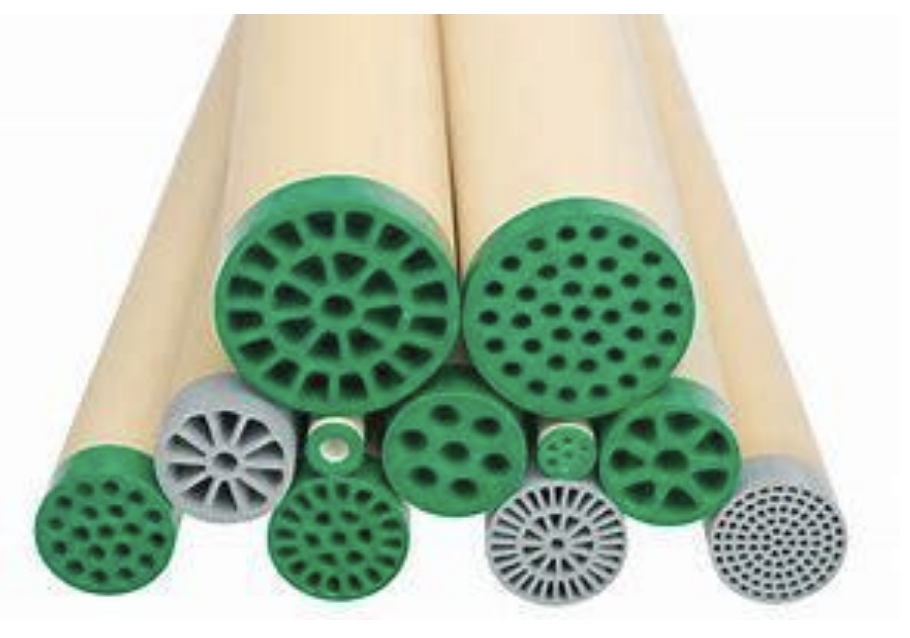
Ceramic membranes of different sections
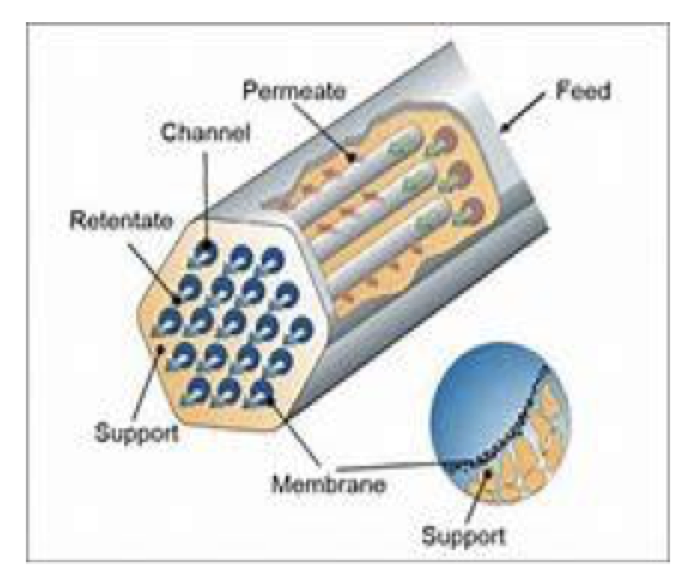
The liquid to be filtered is treated beforehand in a pre-filtration system to prevent obstruction of the membrane channels. The liquid to be treated is fed through the channels that traverse the membrane longitudinally. As shown in the attached diagram, the permeate is obtained by passing the liquid through the walls of the channels and collecting it on the outside of the membrane. The concentrate remains in the channels and passes through the recirculation loop.
Scope of application
Ceramic membranes have a wide scope of application: especially in the food, pharmaceutical, chemical and petrochemical industries, for metal separation in precipitation processes, in pickling and degreasing baths, for beverages (especially wines and beers) and in mining.
In this study we consider them for the field of water treatment. They are used as process water pre-treatment for facilities that require very low turbidity values, such as reverse osmosis. Although they are already being used to filter water for use in microelectronics, as drinking water or in the chemical industry.
They have a very wide range of applications for wastewater. In addition to obtaining high quality permeate, they have many advantages over other classic purification processes, e.g. flotation, decantation and sand filtering, which produce significant waste, have a high consumption of reagents (e.g. coagulants, flocculants and for pH adjustment), widely occupy surfaces and need a lot of manual labor for their maintenance.
In recent years, low cost membranes have been manufactured that can be used in water treatment at competitive costs.
In biological purification, in addition to the reduction of polluting materials in general, the separation of micro plastics and fibers is also considered. For this type of purification and, especially anaerobic, there are already MBRs with ceramic membranes, due to the type of sludge to be treated, their high resistance and due to not contaminating the sludge, which can be sold, thus minimizing the financial cost of purification.
The main sectors in which these membranes are used are:
- Separation and recovery of cutting fluids
- Separation and recovery of fibers and additives in paper industry circuits.
- Recovery and purification of degreasing baths
- Recovery in the paint industry
- Recovery of acids and alkalis in the metal industry
- Separation and recovery of inks
- Separation and recovery of solvents
- Separation and concentration of sugar effluents in sugar factories.
- Separation and concentration of products in the chemical industry.
- Separation and recovery of metals and additives in the electroplating industry.
This type of equipment has a relatively high initial installation cost: as well as the membranes, recirculation pumping units of a significant size are also needed, to achieve adequate tangential speeds to make the process viable. In addition, the materials having to be highly resistant to the media being processed (AISI 316L stainless steel or a higher grade are usually used). However, the expected lifetime of the membranes is very high (> 10 years) and, once the filtration cycles are regulated, they are usually highly reliable, providing few maintenance problems.
Recovery of filtrates and concentrates
Discharging the most polluting effluents into the environment obviously needs to be minimized, and these are precisely the ones treated with this type of membrane. Therefore, the trend must be towards so-called “zero discharge”, as there is no better treatment than zero contamination.
There are many cases in industry, where effluent filtering carried out at the indicated level provides filtrates that are reusable to a greater or lesser extent in the production processes or services of the same company. In addition, the retentate could be reused on many occasions if it had the required concentration and quality, according to the manufacturer’s specifications.
The most suitable technologies to achieve these effects without polluting the effluent are Evaporation and Crystallization.
>High purity distillates are obtained with vacuum evaporation and can often be reused in the factory processes. Evaporation temperatures are often around 50°C, and the heat energy from the condensate can be used for other processes via heat exchangers. Concentrates can reach high levels of dryness, as several stages of evaporation can be implemented.
To the extent that the concentrates acquire significant recycling, their concentration is more justified if crystallized using specific equipment (crystallizer).
The combination of ceramic membranes with evaporation and crystallization provides a highly evolved and efficient technical solution that, when reused, can be considered more as a production process stage than as waste or effluent treatment. Also, the investment cost of the equipment can be viable within an overall financial study of the factory.
The application framework of these solutions is becoming increasingly broad, as technologies are perfected and renewable energies are used.

Ceramic membrane installation calculation
Consider the example of treating washing waste from flexographic ink printing machines. The daily discharge to be treated is 35 m3 at room temperature (about 20ºC).
A sample with a density of 1 is tested and found to have a particle size above 0.05 μm and a density and viscosity similar to that of water.
Tests with ceramic membranes are done and it is found that a speed of 80 L/h/m2is adequate, using a Margarita type UF tubular ceramic membrane (7 channels), with a unit surface area of 0.2 m2, which require a flow rate of 1000 L/memb/m/s, according to the manufacturer tables. Under these conditions, the production cycles between cleanings of the ceramic membrane unit exceed 72 hours, which is considered viable for the process. The objective is to recover the water from the waste, reuse it in the wash and concentrate the separated solid so it can be sent to landfill as waste.
First, we calculate the area needed to filter the entire effluent:
S = (35 m3/d at 24 h/d) / 80 L/h/m2 = 18.6 m2of Margarita type membrane.
Nº. Membranes = 18.6 m2 / 0.2 m2 /membrane = 92 membranes
The manufacturer has two types of casings that can be modified:
- 1 of 99 membranes.
- 2 of 55 membranes.
To select the most appropriate option, an analysis is done of the equipment cost, energy consumption and equipment flexibility.
Equipment cost:
Although a single casing of 99 membranes is more economical than 2 casings of 55, both the recirculation pump unit, and the pipes, valves and fittings are more expensive for the single casing version, as well as the power and electrification panel; so, the cost of both options is quite similar.
Energy consumption:
A flow rate of 1 m3/h/membrane and a recommended circulation velocity in the membranes of 3.5 m/s gives:
1. For 1 casing with 99 membranes:
QR = 1 m3/h/membrane/m/s x 99 membranes x 3.5 m/s = 346.5 m3/h
Using this flow and, to reduce the pressure drop, a circulation speed in the loop of 1.5-2 m/s is taken, then the diameter of the recirculation loop should be 12”.
Assuming the minimum number of valves and pipeline accidents, the load loss of the assembly is approx. 12 mwc.
Power of the pump motor:
Power = (Q x P x 75) / 10000. = (346,5 m3/h x 12 m.c.a x75) / 10000 = 31,18 CV) => We take a 40 HP motor and add a frequency inverter.
2. For 2 casings of 55 membranes arranged in series:
QR = 1 x 55 x 3.5 = 192.5 m3/h and the recirculation loop would be Ø 8”. Under these conditions the load loss for the 2 casings arranged in series would be approx. 18 mwc and the pump motor power:
Power = (192.5 x 18 x 75) / 10000 = 25.98 HP ≥ taking a 30 HP motor.
Thus, it is more energy efficient to use two casings in series
Equipment flexibility:
Although faults are rare in this type of equipment, there may be a leak in a membrane (e.g. in a seal) or a membrane may burst (much less likely). For 2 casings, we could cancel one and work with the other at half flow, which provides flexibility.
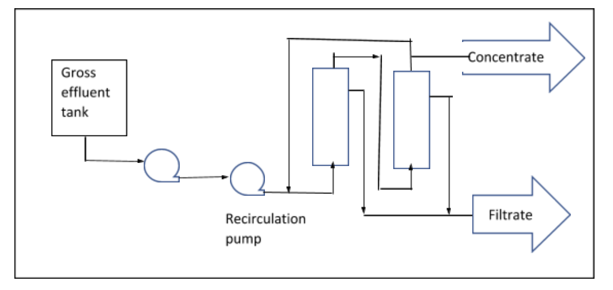
Thus, the choice would be 2 casings in series, according to the following scheme:
Practical considerations
Ceramic membrane equipment is very robust and resistant to extremes of temperature, pressure, alkalinity, acidity and chemical attacks; however, there are some disadvantages to be taken into account:
- Avoid water hammer and impacts because, although the ceramic membranes are very hard, they are also fragile.
- Avoid accidents and valves and instruments that are not strictly necessary in the circulation lines, to avoid load losses resulting in high energy consumption.
- Take into account the equipment construction materials when cleaning or performing a treatment (e.g. not working with HF when there are glass electrodes).
- Do not stretch the filtration cycles, because then cleaning is more difficult.
- The cleaning effluents are usually very contaminated. They should be sent for authorized disposal or concentrated by evaporation and sent to a waste dump suitable for their properties.
- The recirculation pump should have a frequency inverter, so that it consumes the energy strictly necessary at all time.
- When assembling and dismantling the membranes in their casing, special care must be taken to ensure the seals are properly positioned and adjusted.
- Due to the nature of the effluents and reagents handled, the safety regulations must be observed by using the appropriate PPE and additional measures necessary.
