SECTIONS
- Introduction
- Process description
- Scope of application
- Operating conditions
- EDI as an alternative to ion exchange
- EDI pre-treatment
- Summary
INTRODUCTION
In recent years, much research has focused on the developing water treatment technologies without using chemicals, to avoid discharges with high pollutant loads. There are many industrial processes that require very high quality (ultrapure) water. Traditionally, this was obtained by ion exchange technologies using synthetic resins.
Once these were saturated with the salts exchanged in the demineralization process, they had to be regenerated with acid and alkaline reagents, in significant excess to ensure proper performance, before being neutralized and discharged to the environment.
Two complementary systems are currently being used as an alternative to this effective, but polluting, process. These are reverse osmosis (RO) and electrodeionization (EDI), which provide high quality water and remove almost all chemical reagents used in the ion exchange processes.
Electrodeionization (EDI) is a technology that combines two water purification techniques: electrodialysis and ion exchange. Although electrodeionization was described as early as 1957 by Kollsman, it was not until 1987 that it was used in the processes to provide high purity water for the pharmaceutical, microelectronics and energy production industries in high pressure boilers.
After an exhaustive technical review in January 1998, E-Cell electrodeionization technology (known as EDI) began to be used, after a reverse osmosis (RO) process, in the design of basic deionization systems. The continuous electrodeionization process has developed over the last few years to improve equipment performance and its manufacture, by reducing materials and maintenance costs, space requirements and design complexity while improving sanitation.
PROCESS DESCRIPTION
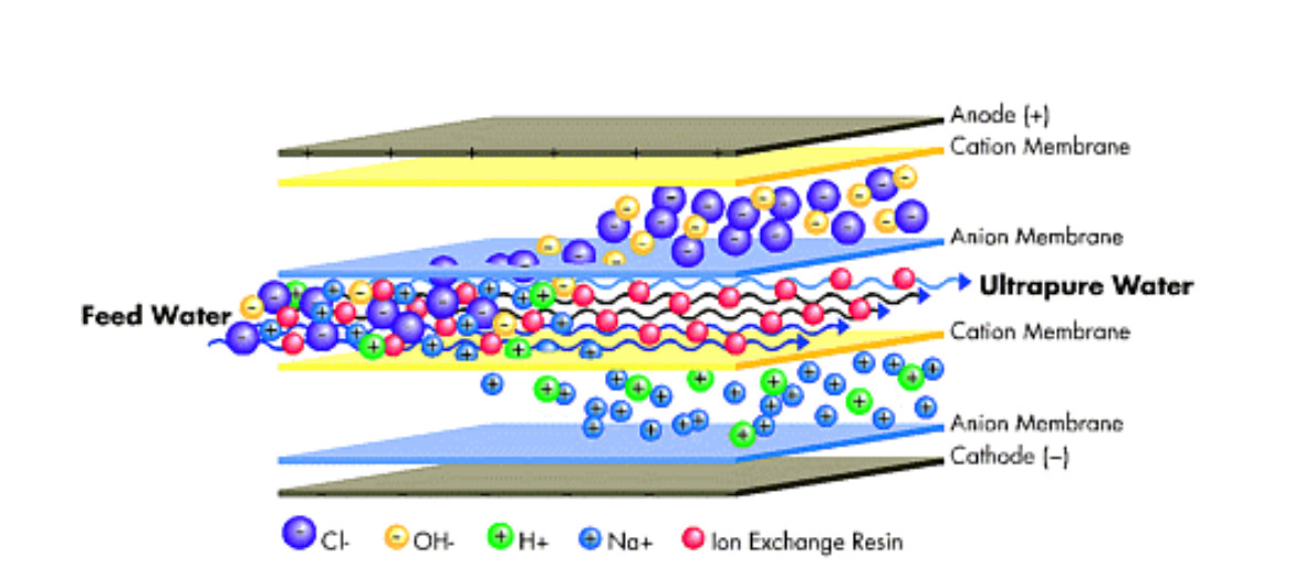
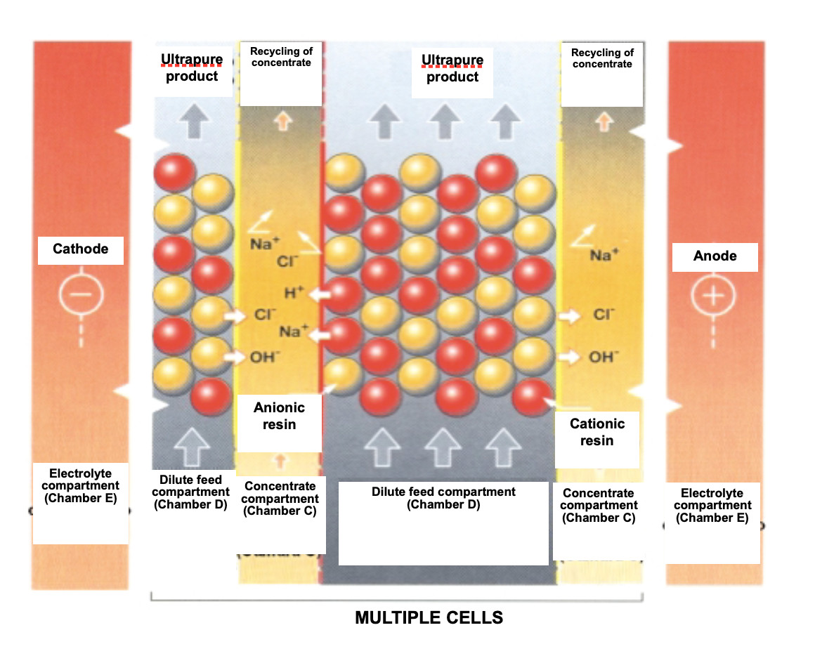
EDI equipment consists basically of a chamber with a strong cationic resin and an anion ion exchange system packed in a space (cell) between a cation exchange membrane and an anion exchange membrane; such that only ions can pass through the membranes.
The water enters through the mixture of ion exchange resins and, at the same time, an external current source feeds direct current through electrodes (cathode and anode).
The direct current voltage creates circulation through the resin that drags the cations towards the cathode and the anions towards the anode. In the path of the ions to the membrane, they can pass into the concentrate chambers, but cannot get any closer to the electrode. They are blocked by the adjoining membrane, which contains a resin of the same fixed load.
Thus, the ion exchange membranes electrically remove the ions from the inlet water and transfer them to the concentrates exiting both ion exchange membranes; thus producing high quality deionized water.
Regeneration of the EDI ion exchange resins
EDI removes ions from the water while the ion exchange resins contained between the membranes are regenerated with an electric current. This electrochemical regeneration uses an electrical potential to carry out ionic transport and replaces the chemical regeneration of conventional ion exchange systems performed, as is known, by acid and sodium hydroxide.
Within the feed compartment, ion exchange resins help transport ions to the concentrate compartment. As the water decreases in ion concentration, dissociation of the water at the cationic and anionic exchange interface occurs, producing a continuous flow of hydrogen and hydroxyl ions. These ions regenerate the ion exchange resins in this compartment and keep the resins at their exit in a highly regenerated state, which is required to produce the desired high quality of the water.
Energy consumption
The cost of operating an EDI system is based on the electrical power it requires. However, almost always, most of the total operating costs are due to the electricity consumed by the RO used as pre-treatment. The average cost for the electricity consumed by EDI is around 0.3 kW/m3 of treated water.
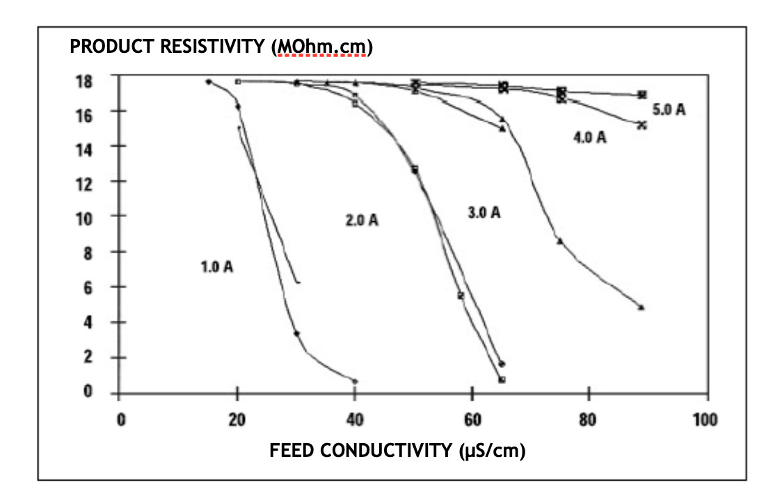
The following graph shows the purifying behavior of EDI according to the quality of the supply water and the current applied. According to the quality of the water obtained, it is practically asymptotic in all indicated cases:
Scope of application
EDI has a wide field of use in the following sectors: Veterinary, Cosmetic, Biotechnology, and those where, in short, it replaces the final treatments for high purity water; however, its priority use in the following three fields should be highlighted:
- Pharmaceutical industry
- Energy industry
- Microelectronics industry
In fact, the modules are manufactured according to their application; consider the following examples:
Pharmaceutical industry
The feed water for many of the processes and washes in the pharmaceutical industry requires very high quality water, as regulated by the different Pharmacopoeial regulations; in particular, the US (USP) and European Pharmacopoeias (PhEur). The US Pharmacopoeia establishes two water qualities: purified water (PW) and water for injections (WFI). The European Pharmacopoeia establishes 3 categories of water: purified water, water for injections and highly purified water.
| US Pharmacopeia specifications | ||
| USP28-NF23 PW Purified Water | ||
| Conductivity | < 1.1 μS/cm at 20ºC | |
| Bacteria | <100 ufc/ml | |
| Total organic carbon TOC | <500 μg C/l | |
| Water for injections (WFI) | ||
| Conductivity | <4.3 μS/cm to 20ºC | <1.1 μS/cm to 20ºC |
| Bacteria | <100 ufc/ml | <10 ufc/100 ml |
| Total organic carbon TOC | <500 μg C/l | <500 μg C/l |
| Endotoxins by LAL | – | <0.25 EU/ml |
The most advanced systems combine the technology of reverse osmosis and continuous electrodeionization in sanitized hot water systems (80ºC) in accordance with the US and European Pharmacopoeia and FDA standards.
Energy Industry
Water treatment for the operation of high pressure boilers and steam generation for electric power production involves designing plants with high quality water production. The conventional design is based on using ion exchange chains with cationic and anionic columns followed by mixed beds that can provide conductivity values below 0.10 μS/cm and a silica (SiO2) concentration below 0.10 μg/L (these parameters are usually required, especially for power generation turbines).
Designs based on a combination of reverse osmosis and continuous electrodeionization have led to a reduction in operating costs, elimination of handling corrosive products, reducing the environmental impact by eliminating cationic and anionic resin regeneration discharges and guaranteeing greater stability in the water quality produced, with respect to the conventional design.
Microelectronics
Semiconductor production in the microelectronics industry also requires water of the highest quality and purity. The quality specifications not only require resistivity values reaching 18 MΩ-c, but also require the reduction of dissolved organic carbon, silica, boron, bacteria, particles over 0.05 μm and metals close to the detection limits.
OPERATING CONDITIONS
For example, the E-Cell™ MK features: Ultrapure water for the energy and semiconductor sectors and industry in general.
| Nominal recovery | 90-95% |
| Energy consumption | 0.05 to 0.4 kWh/m3 |
| Feed pressure | 3.1 to 6.9 bar |
| Water quality produced | > 16 MOhm cm |
| Silica at outlet | < 5ppb |
| Supply voltage | 480VAC/3/60Hz/400VAC 50Hz |
Water quality input and EDI product
| Parameters | RO output | EDI output | EDI, % retention |
| Anions determined by IC (µg/L) | |||
| Chloride | 750 | <0.02 | >99.99 |
| Nitrate | 58 | <0.02 | >99.96 |
| Phosphate | 27 | <0.02 | >99.92 |
| Sulfate | 210 | <0.05 | >99.97 |
| Cations determined by IC (µg/L) | |||
| Sodium | 1100 | 0.24 | >99.97 |
| Ammonium | 7 | <0.05 | >99.28 |
| Potassium | 26 | <0.02 | >99.92 |
| Calcium | 6 | <0.02 | >99.66 |
| Traces of metals determined by ICP-MS (µg/L) | |||
| Aluminum | 0.22 | <0.003 | >98.63 |
| Boron | 13 | <0.05 | >99.61 |
| Lithium | 0.05 | <0.002 | >96.00 |
| Manganese | 0.03 | <0.002 | >93.33 |
| Potassium | 23 | <0.1 | >99.56 |
| Rubidium | 0.04 | <0.001 | >97.50 |
| Sílica | 110 | <0.5 | >99.54 |
| Sodium | 1300 | <0.26 | >99.98 |
| Zinc | 0,09 | <0.005 | >94.44 |
EDI AS AN ALTERNATIVE TO ION EXCHANGE
The classic systems consist basically of exchange columns loaded with cationic resins followed by columns with anionic resins reaching qualities of up to 1 MΩ·cm. If higher quality is required, the system must have additional columns loaded with a mixture of resins and so-called mixed beds, which can produce qualities up to 18 MΩ·cm. High water quality is obtained in such systems, but large amounts of acid and sodium hydroxide are also required for regeneration.
By using reverse osmosis as a pre-treatment for the feed water to the resins, reagent consumption is greatly reduced; however, the current trend is to entirely remove regenerating reagents by having EDI as a final treatment.
EDI is an effective alternative to mixed ion exchange beds placed immediately after a reverse osmosis stage, integrated into a basic deionization train. The RO/EDI combination significantly reduces investment and operating costs.
Some of the advantages of EDI over conventional ion exchange systems are:
- Removal of batch processes and providing consistent water quality
- No operator intervention required
- No complex operating procedures
- Reduces commissioning period for installation in space and time
- Reduces plant requirements
- Low maintenance
- Less space required
- Optimized redundancy
- Easy transportation
- Modularity
- No dangerous rejects
- Discharge neutralization not required
- Reject (Concentrated) recyclable
- Respects the environment
- Helps in ISO 14000 compliance.
The following table proposes a comparison between both deionization systems:
| Electrodeionization | Ionic exchange | |
| Chemical use | No chemicals are handled; regeneration is electrical | Yes, uses alkalis and acids |
| Continuity | Regeneration is continuous | Stand-by equipment needed |
| Water quality | Requires high quality feedwater, < 60 µS/cm | Higher feed water tolerance |
| Water recovery | 80-95% | 95-98% |
| Reject | No hazardous effluents produced, pH neutral and < 300-400 µS/cm | Reject neutralization necessary |
| Maintenance | Electrode changes | Low maintenance |
| CAPEX | Similar costs | Similar costs |
| OPEX | Lower cost, saving in chemicals and regeneration equipment | Higher cost |
EDI PRE-TREATMENT
As commented, although EDI offers important advantages over ion exchange, it also has its limitations; these are basically due to the ease with which it becomes dirty and the high concentration factors obtained (CF = 10), which would represent an equivalent of 90% conversion.
The limitation of input water hardness is very significant for both systems. In mixed beds, total hardness should not exceed 4-5 ppm as CaCO3, while for EDI it is < 1 ppm CaCO3.
Another important parameter, especially for EDI, is free CO2 concentration, as this limits the maximum yield obtained. For example, to achieve a conversion of over 90%, lower than 10 ppm is required; moreover, the concentration of this gas in the reverse osmosis permeate will be significantly higher, because it crosses the membrane on the permeate side and hence the osmotized water pH tends to be acidic, as the balance between HCO3 and CO2 disappears.
There are 2 ways to solve this problem:
Pre-treatment with 2 reverse osmosis steps
This consists of arranging two reverse osmosis steps, with the second being fed the permeate of the first, after adjusting the pH with NaOH.
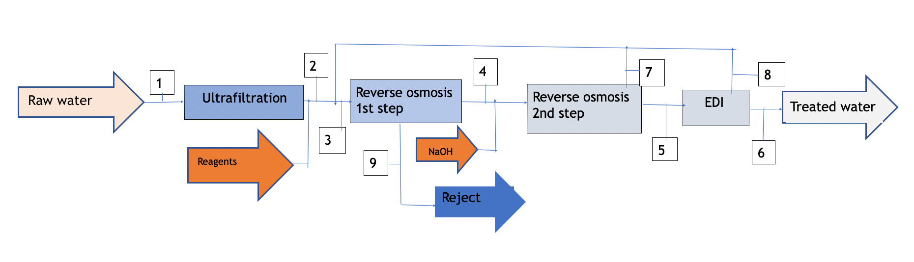
Diagram 1
| Concept | 1 | 2 | 3 | 4 | 5 | 6 | 7 | 8 | 9 |
| TDS (mg/l) | 1000 | 1000 | 800 | 60 | 10 | <0,08 | 65 | 100 | 5000 |
| Q (m3/l) | 10 | 9,8 | 12 | 9,6 | 8,15 | 7,6 | 1,45 | 0,8 | 2,4 |
| Conversion(%) | 98 | 80 | 85 | 93 |
As shown in diagram 1 attached, the process requires a treatment line that begins with ultrafiltration to protect the reverse osmosis membranes. The reject from the first step is discarded (it can be taken to dryness using a vacuum evaporator if zero discharge is desired), The permeate is taken to the second osmosis step after adjusting the pH with NaOH; thus the free CO2 reacts with the NaOH to form Na2CO3,and the resulting permeate from the second step feeds the EDI.
The reject from both the second step and the EDI will have a salinity significantly lower than that of raw water, so it can be recycled at the head of the installation, achieving a global yield of water contribution of the order of 77%.
Pre-treatment with 1 reverse osmosis step
It is always advisable to use high reject (HR) membranes for the reverse osmosis process applied to EDI pre-treatment. In this case, even more so; as the salinity limits cannot be exceeded, as described in point 2.
Depending on the level of HCO3-, the osmotized water will have an excess CO2 content that must be removed. Various degassing means can be used, such as stripping towers, vacuum degassing or Liquid-Cell type membranes for separation. However, the costs justify the installation of a simple CO2 removal system in a conventional stripping tower, calculated with sufficient packing height to obtain the desired level; or, if necessary, with an additional dose of NaOH until its concentration is reduced.
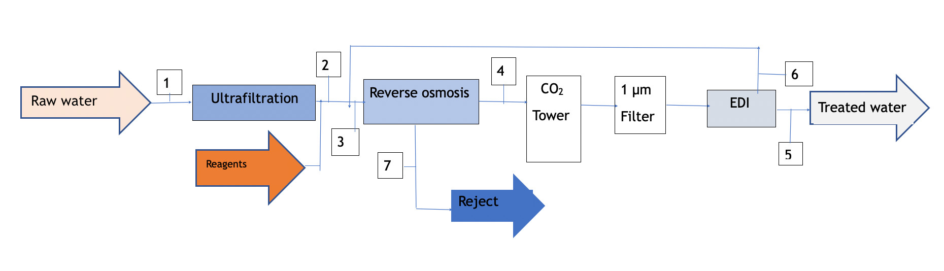
Diagram 2
| Concept | 1 | 2 | 3 | 4 | 5 | 6 | 7 |
| TDS (mg/l) | 1000 | 1000 | 932 | 65 | <0,1 | 110 | 4545 |
| Q (m3/l) | 10 | 9,8 | 10,7 | 8,4 | 7,7 | 0,8 | 2,3 |
| Conversion(%) | 98 | 80 | 90 |
Diagram 2 is a block graph with the balance of flows and salinities obtained with this option. As can be seen, the overall yield from the feed water is similar to the previous type, although the water quality produced is a little lower; however, the installation and operation costs are also lower.
For the pharmaceutical industry, the double-pass reverse osmosis option is normally recommended to prevent possible contamination in the air supply to the atmospheric CO2removal tower; however, the one-step option can be used for the energy and microelectronics industry, depending on the raw water quality obtained for the reverse osmosis phase.
Summary
Although it may seem new, electrodeionization technology has been used in the ultrapure water industry for over 2 decades, and is consolidating its position as the purification system that has practically displaced all other technologies, such as ion exchange, in numerous applications. The future is aimed at improving performance, reducing installation costs and increasing resistance to fouling, so that it can be extended to many other applications. In fact, in recent years, membrane systems have been developed that increase performance and reduce the space previously used by operations with cell systems with flat membranes or stacks.
An indisputable value of the system is its lack of use of reagents, which brings a significant benefit to the environment while also reducing operation costs. Pre-treatment equipment has also evolved, and EDR is taking a prominent role as a pre-treatment for EDI, as it becomes more competitive and efficient.
